2101510MNA H | NGC820 0 AN D PGC 1000 US ER MA NUA L |
119
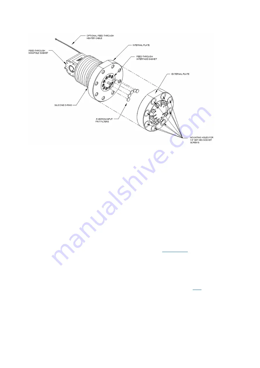
Figure 10-20: Feed-through assembly, exploded view
7.
If the filters appear soiled, it will be necessary to remount the external plate and remove the
input lines. To remove the input lines, continue to the next step; otherwise, move to step 9.
8.
Using a ¼” open end wrench, loosen the nut, and remove the input line. Repeat for all sample,
carrier and calibration gas lines.
9.
Remove the 8–¼” hex socket mounting screws.
10. Remove the used filters from the filter sockets. Using an edged instrument or fingernail, put
pressure on the outermost edge of each filter to pop them out.
11. If replacing filters due to clogging, use compressed air to blow out the input holes in the
external plate. It may also be necessary to wipe clean the gasket located on the internal plate;
otherwise, move to the next step.
12. Using the replacement filter, carefully lay the filter into the filter socket, applying uniform
pressure to the filter. Do not use any pointed instrument to push the filter into place. Repeat
for each input stream, carrier and calibration gas input. Vents do not require filters.
13. Reseat the external plate, aligning the mounting pins on the internal plate to the corresponding
holes on the external plate.
14. Replace the 8–¼” mounting screws, using a star pattern when tightening the screws.
15. If the sample, carrier and calibration gas lines were removed, purge the air from the transport
tubing and reconnect to the corresponding ports. Do not over-tighten.
16. After securing the tubing, check for gas leaks.
10.22 Replace the feed-through interface gasket
Should the feed-through interface gasket require replacement (see
), follow these
instructions. Typically, the user would change the gasket while performing another procedure, but for
the purposes of this manual, the instructions will start and finish as a complete procedure.
To replace the feed-through interface gasket:
1.
On the Analyzer Operation screen, click
Hold
under Next Mode. When the device completes the
current cycle and enters hold, continue to the next step.
2.
Collect data from the device.
3.
Back up the configuration files, following the instructions detailed in section
.
4.
Turn off all the sample streams, calibration gas and carrier gas.
5.
Using a 7/32” hex wrench, loosen and remove all 8 ¼” hex socket screws.
6.
If space permits, lift the external plate away from the internal plate and remove the damaged
gasket from the internal plate. If space does not permit lifting the plate away enough to replace
the gasket, remove the sample input lines and the carrier and calibration gas lines.
7.
Remount the external plate and remove the input lines. To remove the input lines, continue to
the next step; otherwise, skip to step 9.
8.
Using a ¼” open end wrench, loosen the nut and remove the input line. Repeat for all sample,
carrier and calibration gas lines.


