


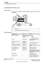


Removal, motor, axis 5
The procedure below details how to remove motor, axis 5.
Note
Action
Decide which calibration routine to use, and take
actions accordingly prior to beginning the repair
procedure.
1
DANGER
Turn off all:
•
electric power supply to the robot
•
hydraulic pressure supply to the robot
•
air pressure supply to the robot
Before entering the robot working area.
2
Detailed in the section
.
Drain the oil from gearbox axis 5.
3
Detailed in the section
.
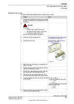
xx1400002580
Remove the wrist unit.
4
Place the wrist unit safely on a workbench, in a
fixture or similar.
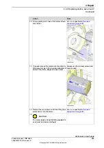
5
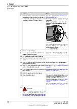
Remove the cover on top of the motor by unscrew-
ing its four attachment screws.
6
Remove the cable gland cover at the cable exit
by unscrewing its two attachment screws.
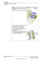
7
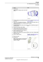
Disconnect all connectors beneath the motor
cover and remove the cable of the axis-5 motor.
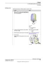
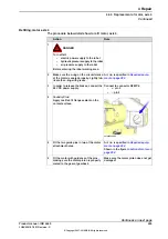
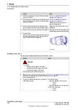
8
Connect to either:
In order to release the brake, connect the 24 VDC
power supply.
9
- connector R4.MP5 (in the motor):
•
+ : pin 2
•
-: pin 5
- connector R3.MP5 (on the separate
cable, if not removed):
•
+: pin C
•
-: pin D
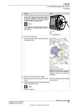
Remove the motor by unscrewing its four attach-
ment screws and plain washers.
10
Continues on next page
Product manual - IRB 6660
299
3HAC028197-001 Revision: S
© Copyright 2007-2018 ABB. All rights reserved.
4 Repair
4.6.4 Replacement of motor, axis 5
Continued
Summary of Contents for IRB 6660
Page 1: ...ROBOTICS Product manual IRB 6660 ...
Page 8: ...This page is intentionally left blank ...
Page 18: ...This page is intentionally left blank ...
Page 48: ...This page is intentionally left blank ...
Page 108: ...This page is intentionally left blank ...
Page 172: ...This page is intentionally left blank ...
Page 366: ...This page is intentionally left blank ...
Page 386: ...This page is intentionally left blank ...
Page 388: ...This page is intentionally left blank ...
Page 394: ......
Page 395: ......


