background image

4 Repair

4.7.2. Replacement gearbox axis 2

3HAC027151-001  Revision: B

236

© 

Co

py

rig

h

t 200

6-

200

8 ABB. All righ

ts reser

v

ed.

Removal

The procedure below details how to remove gearbox axis 2.

Other tools and 
procedures may be 
required. See 
references to these 
procedures in the step-
by-step instructions 
below. 

These procedures include 
references to the tools 
required. 

Equipment, etc

Spare part 
no.

Art. no.

Note

Action

Note

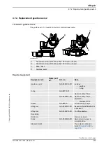
1. Move the robot to the position, shown in the 

figure to the right.

xx0600003125

2.

DANGER!

Turn off all electric power, hydraulic and 
pneumatic pressure supplies to the robot!

3. Drain the oil from gearbox axis 2.

Detailed in section 

Oil change, 

gearbox axis 2 on page 129

.

4.

CAUTION!

The upper and lower arms (incl. gearboxes 
axes 2 and 3) weighs 455 kg. All lifting 
equipment used must be sized accordingly!

Continued

Continues on next page

Summary of Contents for IRB 6620 - 150/2.2

Page 1: ...Product manual Articulated robot IRB 6620 150 2 2 M2004 ...

Page 2: ......

Page 3: ... Copyright 2006 2008 ABB All rights reserved Product manual IRB 6620 150 2 2 M2004 Document ID 3HAC027151 001 Revision B ...

Page 4: ...sons or property fitness for a specific purpose or the like In no event shall ABB be liable for incidental or consequential damages arising from use of this manual and products described herein This manual and parts thereof must not be reproduced or copied without ABB s written permission and contents thereof must not be imparted to a third party nor be used for any unauthorized purpose Contravent...

Page 5: ...n safety and information labels 29 1 3 Safety related instructions 30 1 3 1 Safety signals general 30 1 3 2 DANGER Moving robots are potentially lethal 32 1 3 3 DANGER First test run may cause injury or damage 33 1 3 4 WARNING The brake release buttons may be jammed after service work 34 1 3 5 WARNING The unit is sensitive to ESD 35 1 3 6 WARNING Safety risks during work with gearbox oil 36 2 Inst...

Page 6: ... axes 2 5 118 3 3 12 Inspection signal lamp 120 3 4 Replacement changing activities 122 3 4 1 Type of oil in gearboxes 122 3 4 2 Oil change gearbox axis 1 126 3 4 3 Oil change gearbox axis 2 129 3 4 4 Oil change gearbox axis 3 132 3 4 5 Oil change gearbox axis 4 135 3 4 6 Oil change gearbox axis 5 137 3 4 7 Oil change gearbox axis 6 139 3 4 8 Replacement of SMB battery 142 3 5 Cleaning activities ...

Page 7: ...9 5 2 Calibration methods 250 5 3 Calibration scales and correct axis position 252 5 4 Calibration movement directions for all axes 253 5 5 Updating revolution counters 254 5 6 Checking the calibration position 256 6 Decommissioning 257 6 1 Environmental information 257 7 Reference information 259 7 1 Applicable Safety Standards 259 7 2 Unit conversion 260 7 3 Screw joints 261 7 4 Weight specifica...

Page 8: ...Table of Contents 6 3HAC027151 001 Revision B Copyright 2006 2008 ABB All rights reserved ...

Page 9: ...f mechanical and electrical installation repair maintenance work Organization of chapters The manual is organized in the following chapters Chapter Contents Safety Safety information that must be read through before performing any installation or service work on robot Contains general safety aspects as well as more specific information on how to avoid personal injuries and damage to the product In...

Page 10: ...8 1 Operating manual Service Information System 3HAC025709 001 Application manual Additional axes and stand alone controller 3HAC021395 001 Technical reference manual System parameter 3HAC17076 1 Revision Description First edition A Changes made in Prerequisites in section Overview Oil change in section Maintenance B Changes made in Oil change Shell Tivela S 150 is changed to Kyodo Yushi TMO 150 N...

Page 11: ...ures including spare parts Additional procedures if any calibration decommissioning Reference information article numbers for documentation referred to in Product manual procedures lists of tools safety standards Part list Foldouts or exploded views Circuit diagrams Technical reference manuals The following manuals describe the robot software in general and contain relevant reference information R...

Page 12: ...d at those having first hand operational contact with the robot that is production cell operators programmers and trouble shooters The group of manuals includes Emergency safety information General safety information Getting started IRC5 IRC5 with FlexPendant RobotStudio Introduction to RAPID Trouble shooting for the controller and robot Continued ...

Page 13: ...nclude references to equipment spare parts tools etc required for the different actions in the procedure The equipment is marked with italic text in the procedures and completed with a reference to the section where the equipment is listed with further information that is article number dimensions The denomination in the procedure for the component or attachment point corresponds to the denominati...

Page 14: ...How to read the product manual 3HAC027151 001 Revision B 12 Copyright 2006 2008 ABB All rights reserved ...

Page 15: ...rtant to attend to before performing any service work on the robot These are applicable for all service work and are found in section General safety information specific safety information pointed out in the procedure at the moment of the danger How to avoid and eliminate the danger is either detailed directly in the procedure or further detailed in separate instructions found in section Safety re...

Page 16: ...tion and handling of the industrial robot described in the applicable documents for example Operating Manual IRC5 with FlexPendant M2004 Product Manual Connection of external safety devices Apart from the built in safety functions the robot is also supplied with an interface for the connection of external safety devices Via this interface an external safety function can interact with other machine...

Page 17: ...t be crossed before admittance must be set up in front of the robot s working space Light beams or sensitive mats are suitable devices Turntables or the like should be used to keep the operator out of the robot s working space The axes are affected by the force of gravity when the brakes are released In addition to the risk of being hit by moving robot parts you run the risk of being crushed by th...

Page 18: ...lt in burns too Removed parts may result in collapse of robot WARNING Take any necessary measures to ensure that the robot does not collapse as parts are removed e g secure the lower arm with fixtures if removing motor axis 2 Safety risk Description Cable packs are sensitive to mechanical damage CAUTION The cable packs are sensitive to mechanical damage They must be handled with care especially th...

Page 19: ...safely turn off tools such as milling cutters etc Make sure that guards remain closed until the cutters stop rotating It should be possible to release parts by manual operation valves Safe design Grippers end effectors must be designed so that they retain workpieces in the event of a power failure or a disturbance of the controller CAUTION Ensure that a gripper is prevented from dropping a workpie...

Page 20: ... to pneumatic and hydraulic systems Residual energy Residual energy may be present in these systems After shutdown particular care must be taken The pressure in pneumatic and hydraulic systems must be released before starting to repair them Safe design Gravity may cause any parts or objects held by these systems to drop Dump valves should be used in case of emergency Shot bolts should be used to p...

Page 21: ...rried out professionally and in accordance with the applicable safety regulations Care must be taken at all times Qualified personnel Corrective maintenance must only be carried out by qualified personnel who are familiar with the entire installation as well as the special risks associated with its different parts Extraordinary risks If the working process is interrupted extra care must be taken d...

Page 22: ...om an external source The mains supply mains switch The transformers The power unit The control power supply 230 VAC The rectifier unit 400 480 VAC and 700 VDC Note Capacitors The drive unit 700 VDC The drive system power supply 230 VAC The service outlets 115 230 VAC The customer power supply 230 VAC The power supply unit for additional tools or special power supply units for the machining proces...

Page 23: ...mension the fence or enclosure to enable it to withstand the force created if the load being handled by the robot is dropped or released at maximum speed Determine the maximum speed from the maximum velocities of the robot axes and from the position at which the robot is working in the work cell see Product Specification Description Robot Motion Also consider the maximum possible impact caused by ...

Page 24: ...e extinguishing 3HAC027151 001 Revision B 22 Copyright 2006 2008 ABB All rights reserved 1 2 3 2 Fire extinguishing NOTE Use a CARBON DIOXIDE CO2 extinguisher in the event of a fire in the robot system robot or controller ...

Page 25: ...eased manually by pushing the brake release buttons on the robot How to release the brakes is detailed in section Manually releasing the brakes on page 61 The robot arm may be moved manually on smaller robot models but larger models may require using an overhead crane or similar Increased injury Before releasing the brakes make sure that the weight of the arms does not increase the pressure on the...

Page 26: ...m its function How to test The function of the holding brake of each axis motor may be checked as detailed below 1 Run each robot axis to a position where the combined weight of the robot arm and any load is maximized max static load 2 Switch the motor to the MOTORS OFF position with the Operating mode selector on the controller 3 Check that the axis maintains its position If the robot does not ch...

Page 27: ...1 001 Revision B Copyright 2006 2008 ABB All rights reserved 1 2 3 5 Risk of disabling function Reduced speed 250 mm s NOTE Do not change Transm gear ratio or other kinematic system parameters from the FlexPendant or a PC This will affect the safety function Reduced speed 250 mm s ...

Page 28: ... him her when entering the robot s working space This is to prevent anyone else taking control of the robot without the programmer knowing Enabling device The enabling device is a manually operated constant pressure push button which when continuously activated in one position only allows potentially hazardous functions but does not initiate them In any other position hazardous functions are stopp...

Page 29: ...ntrol panel The robot s speed is limited to max 250 mm s when the operating mode selector is in position manual mode with reduced speed This should be the normal position when entering the working space The position manual mode with full speed 100 may only be used by trained personnel who are aware of the risks that this entails Pay attention to the rotating axes of the robot Keep a distance to th...

Page 30: ...reserved 1 2 3 8 Signal lamp optional Description A signal lamp with an yellow fixed light can be mounted on the robot as a safety device Function The lamp is active in MOTORS ON mode Further information Further information about the MOTORS ON MOTORS OFF mode may be found in the controller documentation ...

Page 31: ...o the product contain space for adding a fourth language underneath the three standard languages English German and French Add a local language to the label by Using a transparent sticker over the standard label with text added in a fourth language Drawings detailing the design text figure dimensions of the standard labels can be ordered from ABB Notice that each label is identified according to t...

Page 32: ...h for example contact with high voltage electrical units explosion or fire risk risk of poisonous gases risk of crushing impact fall from height etc warning WARNING Warns that an accident may occur if the instructions are not followed that can lead to serious injury possibly fatal and or great damage to the product It applies to warnings that apply to danger with for example contact with high volt...

Page 33: ...lectrostatic discharge ESD symbol indicates electrostatic hazards which could result in severe damage to the product Note NOTE Note symbols alert you to important facts and conditions Tip TIP Tip symbols direct you to specific instructions where to find additional information or how to perform a certain operation in an easier way Symbol Designation Signification Continued ...

Page 34: ...ction Note 1 Before attempting to run the robot make sure all emergency stop equipment is correctly installed and connected Emergency stop equipment such as gates tread mats light curtains etc 2 Usually the hold to run function is active only in manual full speed mode To increase safety it is also possible to activate hold to run for manual reduced speed with a system parameter The hold to run fun...

Page 35: ... to take into consideration before the first test run Elimination Follow the procedure below when performing the first test run after a service activity repair installation or maintenance Action 1 Remove all service tools and foreign objects from the robot and its working area 2 Install all safety equipment properly 3 Make sure all personnel are standing at a safe distance from the robot that is o...

Page 36: ...se the power is turned on while a brake release button is jammed in depressed position the affected motor brake is released This may cause serious personal injuries and damage to the robot Elimination To eliminate the danger after service work has been performed inside the SMB recess follow the procedure below Action 1 Make sure the power is turned off 2 Remove the push button guard if necessary 3...

Page 37: ...ot grounded may potentially transfer high static charges This discharge may destroy sensitive electronics Elimination Location of wrist strap button The wrist strap button is located in the right corner as shown in the illustration below xx0500002171 Action Note 1 Use a wrist strap Wrist straps must be tested frequently to ensure that they are not damaged and are operating correctly 2 Use an ESD p...

Page 38: ...the opening Do not overfill the gearbox when filling Do not overfill Overfilling of gearbox oil can lead to internal over pressure inside the gearbox which in turn may damage seals and gaskets completely press out seals and gaskets prevent the robot from moving freely Make sure not to overfill the gearbox when filling with oil After filling check the correct oil level Do not mix types of oil Mixin...

Page 39: ...erved 2 Installation and commissioning 2 1 Introduction General This chapter contains information for installing the robot to the working site More detailed technical data such as load diagram permitted extra loads equipment and location of extra loads equipment can be found in the Product specification for the robot ...

Page 40: ...side the plant must be carried out according to description in method 1 If transportation according to method 1 is not possible use method 2 Transportation in any other way than method 1 or 2 can seriously damage the robot If the robot is incorrectly transported and the instructions are not followed the robot is not covered by the warranty and ABB will not accept any compensation claim Method 1 Tr...

Page 41: ... instructions in section Pre installation procedure on page 47 Method 2 Transportation according to method 2 is approved by ABB if use of method 1 is not possible Always follow these instructions when transporting an ABB robot according to method 2 Always read and follow the instructions in section Securing the robot on page 45 Always place the robot in the ABB recommended transport position for r...

Page 42: ...portation precautions 3HAC027151 001 Revision B 40 Copyright 2006 2008 ABB All rights reserved IRB7600 IRB66XX xx0800000037 A Transport Support B Hexagon socket head cap screw M16x140 C Threaded bar M10x200 D Nut M10 Continued Continues on next page ...

Page 43: ...rtation precautions 41 3HAC027151 001 Revision B Copyright 2006 2008 ABB All rights reserved IRB6620 Foundry Plus xx0800000036 A Transport Support B Hexagon socket head cap screw M10x50 C Threaded bar M10x280 D Nut M10 Continued Continues on next page ...

Page 44: ...autions 3HAC027151 001 Revision B 42 Copyright 2006 2008 ABB All rights reserved Transport position with a transport support All transportation of the robot with tool must follow these instructions IRB 6620 Foundy Plus xx0800000041 Continued Continues on next page ...

Page 45: ...precautions 43 3HAC027151 001 Revision B Copyright 2006 2008 ABB All rights reserved Recommended transport support Always use the recommended transport support when transporting a robot with tool IRB 7600 IRB 66XX xx0800000039 Continued Continues on next page ...

Page 46: ...2 Installation and commissioning 2 2 Robot transportation precautions 3HAC027151 001 Revision B 44 Copyright 2006 2008 ABB All rights reserved IRB 6620 xx0800000038 Continued ...

Page 47: ...ing the brakes is a hazardous action that may cause injury and damage property It must be done with great care and only when absolutely necessary Securing the robot xx0800000062 Action Note 1 Mount the transport support lower end to the robot using the recommended screw joint A in figure Do not tightening the screw See attachment point for the specific robot in section Transport position with a tr...

Page 48: ...al resting position on the transport support see section Manually releasing the brakes on page 61 See attachment point for the specific robot in section Transport position with a transport support on page 42 4 Tightening all the attachment screws A and B in figure with the brake release for axis 3 still activated starting with the lower end attachment screw CAUTION Do not attempt to tightening any...

Page 49: ...Make sure only qualified installation personnel conforming to all national and local codes are allowed to perform the installation 2 Visually inspect the robot to make sure it is not damaged 3 Make sure the lifting device used is suitable to handle the weight of the robot as specified in Weight robot on page 47 4 If the robot is not installed directly it must be stored as described in Storage cond...

Page 50: ...tection class of the robot Torque xy 19 0 kNm 18 0 kNm 32 5 kNm 37 2 kNm Torque z 4 4 kNm 10 4 kNm Force Endurance load operation Max load emergency stop Requirement Value Note Min levelity 0 5 mm Max tilt 15 The limit for the maximum load on the robot is reduced if the robot is tilted Contact ABB for further information about acceptable loads Min resonance frequency 22 Hz Parameter Value Min ambi...

Page 51: ...range and type of motion Working range The following figures show the working ranges of the robot model mounted in different ways The extreme positions of the robot arm are specified at the wrist center dimensions in mm Floor mounted The illustration below shows the unrestricted working range when the robot is floor mounted xx0600002906 Continues on next page ...

Page 52: ...e and type of motion 3HAC027151 001 Revision B 50 Copyright 2006 2008 ABB All rights reserved Suspended mounted The illustration below shows the unrestricted working range when the robot is mounted suspended xx0600002907 Continued Continues on next page ...

Page 53: ... B Copyright 2006 2008 ABB All rights reserved Floor mounted in 15 angle The illustration below shows the unrestricted working range when the robot is floor mounted in 15 angle xx0600002908 A Note Maximum tilt angle is 15 B Intersection between base and axis 1 center Continued Continues on next page ...

Page 54: ...gure below xx0600002909 Type of motion The default working range can be extended by changing parameter values in the software Option Advanced Motion is required Axis Type of motion Range of movement Note 1 Rotation motion 170 to 170 2 Arm motion 140 to 65 3 Arm motion 70 to 115 Limitations with dresspack 4 Wrist motion 300 to 300 5 Bend motion 130 to 130 Limitations with dresspack 6 Turn motion 30...

Page 55: ...d standing still the robot is not stable in the whole working area Moving the arms will displace the center of gravity which may cause the robot to tip over Do not change the robot position before securing it to the foundation Stabililty The figure below shows the robot in its shipping position which also is its most stable position xx0600002935 WARNING The robot is likely to be mechanically unsta...

Page 56: ...at available special aids are used This section describes how to attach the fork lift equipment to the robot Fork lift device set The fork lift device set is fitted to the robot as shown in the figure below xx0600002910 Required equipment A Fork lift pocket B Attachment screw M20x50 quality 8 8 2 pcs x 4 Equipment etc Art no Note Fork lift device set 3HAC025040 003 Standard toolkit The content is ...

Page 57: ... and move it using fork lift ONLY The illustration below shows the position of the robot when lifting it with fork lift xx0600002911 Action Note 1 Move the robot to the position as shown in the figure above NOTE No load is permitted on the robot Release the brakes if required as detailed in section Manually releasing the brakes on page 61 2 DANGER Turn off all electric power hydraulic and pneumati...

Page 58: ...sure the original screws are always used or replacements of equivalent quality M20x50 quality 8 8 Attachment points on the robot are shown in the figure below xx0600002927 A Attachment holes for fork lift 4 Double check that all four fork lift pockets are properly secured before lifting xx0600002930 A Fork lift pocket B Attachment screw M20x50 quality 8 8 2 pcs x 4 Tightening torque 300 Nm Action ...

Page 59: ...d 5 Insert the fork lift forks into the pockets 6 CAUTION The robot weighs 900 kg All lifting equipment used must be sized accordingly 7 Carefully lift the robot and move it to its installation site NOTE Move the robot with low speed 8 WARNING Personnel must not under any circum stances be present under the suspended load Action Note Continued ...

Page 60: ... The illustration is identical with the label attached to the robot s lower arm Attachment points The figure below shows how to attach the roundslings to the robot xx0600002921 Sling specification A Roundsling upper arm 2 5 m B Roundsling upper arm 2 m C Roundsling robot 2 5 m 4 pcs D Lifting eye M20 4 pcs E Holes for lifting eyes in the robotbase Rear holes Sling type Qty Lifting capacity Length ...

Page 61: ...ifting eye bolts in the rear M20 holes Shown in figure Attachment points on page 58 3 NOTE Make sure that the roundslings do not lie against sensitive parts for example harness and customer equipment 4 When attaching the roundsling A on the upper arm put it in a U shape through the hole in the wrist Shown in the figure Attachment points on page 58 5 When attaching the roundsling B on the upper arm...

Page 62: ...ioning 2 5 2 Lifting robot with roundslings 3HAC027151 001 Revision B 60 Copyright 2006 2008 ABB All rights reserved 8 WARNING Personnel must not under any circumstances be present under the suspended load Action Note Continued ...

Page 63: ... located on the frame beside motor axis 1 The internal brake release unit is equipped with six buttons for controlling the axes brakes The buttons are numbered according to the numbers of the axes If the robot is not connected to the controller power must be supplied to the connector R1 MP according to section Supplying power to connector R1 MP on page 62 The buttons are shown in the figure Locati...

Page 64: ...r R1 MP If the robot is not connected to the controller power must be supplied to connector R1 MP in the robot base in order to enable the brake release buttons on the robot Action Note 1 DANGER Incorrect connections such as supplying power to the wrong pin may cause all brakes to be released simultaneously 2 Supply 0V on pin 12 and 24V on pin 11 xx0600002937 Continued ...

Page 65: ...fting base plate Equipment Art no Note Lifting eye M16 3HAC14457 4 3 pcs Lifting slings 3 pcs Length approx 2 m A Attachment holes for lifting eyes x3 Action Note 1 CAUTION The base plate weighs 353 kg All lifting equipment used must be sized accordingly 2 Fit the lifting eyes in the three lifting holes Shown in the figure Hole con figuration on page 63 3 Fit the lifting slings to the eyes and to ...

Page 66: ...ecuring the base plate 3HAC027151 001 Revision B 64 Copyright 2006 2008 ABB All rights reserved 2 5 5 Securing the base plate General This section details how to secure the base plate Base plate dimensions xx0100000105 Continues on next page ...

Page 67: ...on and commissioning 2 5 5 Securing the base plate 65 3HAC027151 001 Revision B Copyright 2006 2008 ABB All rights reserved xx0400000715 A Four holes for alternative clamping 4x Ø18 Continued Continues on next page ...

Page 68: ...s attachment holes 4 pcs Equipment Art no Note Base plate 3HAC12937 9 Includes guide sleeves 3HAC12937 3 levelling screws 9ADA120 79 attachment screws and washers for securing the robot to the base plate A drawing of the base plate itself may be ordered from ABB Robotics Standard toolkit The content is defined in section Standard toolkit on page 265 Other tools and procedures may be required See r...

Page 69: ...tion to the robot work location using the three grooves in the base plate Shown in the figure Base plate grooves and holes on page 66 4 Lift the base plate to its mounting position Detailed in section Lifting the base plate on page 63 5 Use the base plate as a template and drill 16 attachment holes as required by the selected bolt dimension If possible observe the recommenda tions specified in sec...

Page 70: ...te The illustration below shows the robot base fitted to the base plate xx0600002933 Attachment screws The table below specifies the type of securing screws and washers to be used for securing the robot to the base plate foundation A Robot attachment bolts and washers 8 pcs M24 x 100 B Orienting grooves in the robot base and in the base plate C Levelling screws Note Remove before the robot base is...

Page 71: ...location 3 Fit two guide sleeves to the guide sleeve holes in the base plate NOTE One of the guide sleeve holes is elongated 4 Guide the robot gently using two M24 screws while lowering it into its mounting position Make sure the robot base is correctly fitted onto the guide sleeves 5 Fit the bolts and washers in the base attachment holes Specified inAttachment screws on page 68 Shown in the figur...

Page 72: ...n B 70 Copyright 2006 2008 ABB All rights reserved Hole configuration base The illustration below shows the hole configuration used when securing the robot xx0600002932 Cross section guide sleeve hole The illustration below shows the cross section of the guide sleeve holes xx0600002934 Continued ...

Page 73: ...acceptable vibrations and deflections so that optimum performance can be achieved System parameters If the robot is mounted at any other angle the system parameter gravity beta must be updated Gravity beta specifies the robot s mounting angle expressed in radians NOTE It is very important to configure gravity beta correctly so that the robot system can control the movements in the best possible wa...

Page 74: ...bot s mounting angle in radians It is calculated in the following way for a mounting angle of 15 Gravity beta 15 x 3 141593 180 0 261799 radians xx0600003144 Example of position Mounting angle Gravity beta Floor A 0 0 000000 Default Tilted B 15 0 261799 Suspended C 180 3 141593 A Floor mounted B Tilted mounting mounting angle 15 C Suspended mounting mounting angle 180 Continued Continues on next p...

Page 75: ...gs to the type Robot in the topic Motion How to calculate a new value is detailed in Mounting angles and values on page 72 The parameter is further detailed in the Technical reference manual System parameters The parameter can be edited either with the FlexPendant or in RobotStudio Read about how to change the parameter in the Operating manual IRC5 with FlexPendant or in the Operating manual Robot...

Page 76: ...may be obstructed by any additional cabling equipment etc fitted by the robot user Make sure the required mounting holes are accessible when planning the robot cell Illustration fitting of extra equipment on lower arm The illustrations below shows the mounting holes available for fitting extra equipment on the lower arm Make sure not to damage the robot cabling on the lower arm when fitting extra ...

Page 77: ...2 Installation and commissioning 2 5 8 Fitting equipment on robot 75 3HAC027151 001 Revision B Copyright 2006 2008 ABB All rights reserved xx0600002944 Continued Continues on next page ...

Page 78: ...027151 001 Revision B 76 Copyright 2006 2008 ABB All rights reserved Illustration fitting of extra equipment on upper arm The illustrations below shows the mounting holes available for fitting extra equipment on the upper arm xx0600002941 Continued Continues on next page ...
Page 79: ...2 Installation and commissioning 2 5 8 Fitting equipment on robot 77 3HAC027151 001 Revision B Copyright 2006 2008 ABB All rights reserved xx0600002945 Continued Continues on next page ...

Page 80: ...3HAC027151 001 Revision B 78 Copyright 2006 2008 ABB All rights reserved Illustration fitting of extra equipment on frame The illustrations below shows the mounting holes available for fitting extra equipment on the frame xx0600002947 Continued Continues on next page ...

Page 81: ...2 Installation and commissioning 2 5 8 Fitting equipment on robot 79 3HAC027151 001 Revision B Copyright 2006 2008 ABB All rights reserved xx0600002950 Continued Continues on next page ...

Page 82: ...hts reserved Illustration fitting on turning disk The illustration below shows the mounting holes available for fitting equipment on the turning disk xx0200000397 Turning disk for robot version IRB6620 150 2 2 Use every other of the bolt holes for six attachment bolts as numbered in the figure Continued Continues on next page ...

Page 83: ...027151 001 Revision B Copyright 2006 2008 ABB All rights reserved xx0200000197 Fastener quality When fitting tools on the turning disk see the figures above only use screws with quality 12 9 When fitting other equipment standard screws with quality 8 8 may be used Continued ...

Page 84: ...nts and overloading motors gears and structure CAUTION Incorrect defined loads may result in operational stops or major damage on the robot References Load diagrams permitted extra loads equipment and their positions are specified in the Product Specification The loads must also be defined in the software as detailed in Operating manual IRC5 with FlexPendant Stop time and braking distances Robot m...

Page 85: ...hat it may collide with other objects its working space should be limited The working range of the following axes may be restricted Axis 1 hardware mechanical stop and software Axis 3 hardware mechanical stop and software As a standard configuration axis 1 is allowed to move 170 This section describes how to install hardware that restricts the working range Notice that adjustments must also be mad...

Page 86: ...fixed mechanical stops and can be reduced by adding additional mechanical stops giving 7 5 or 15 graduation between 22 5 and 135 in both directions Mechanical stops axis 1 The illustration below shows the mounting position of the stop pin and one of the additional mechanical stops available for axis 1 xx0600002938 A Movable mechanical stop B Attachment screw plus washer M12 x 40 quality 12 9 2 pcs...

Page 87: ...C025367 001 attachment screws and washers document for movable mech stop 3HAC025408 001 Movable mechanical stop set axis 1 7 5 15 3HAC025204 003 Includes two stops 15 7 5 3HAC025366 001 two stops 7 5 15 3HAC025367 001 attachment screws and washers document for movable mech stop 3HAC025408 001 Standard toolkit The content is defined in section Standard toolkit on page 265 Technical reference manual...

Page 88: ... be re defined The motion configuration parameter arm rob1_1 Upper Joint Bound and arm rob1_1 Lower Joint Bound must be changed to 3 84 resp 3 84 The values are in radians that is 220 deg 3 84 rad The system parameters that must be changed in RobotWare 5 0 Upper joint bound and Lower joint bound are further detailed in Technical reference manual System parameters 4 WARNING If the mechanical stop i...

Page 89: ...ing over Mechanical stops axis 3 The illustration below shows the mounting position of the mechanical stops on axis 3 xx0600002939 Required equipment A Mechanical stop pin axis 3 B Attachment screw plus washer Equipment etc Art no Note Mechanical stop set axis 3 3HAC025290 003 Includes one mechanical stop pin 3HAC025092 001 attachment screw and washer document for Mech stop pin 3HAC025409 001 Stan...

Page 90: ...ydraulic and pneumatic pressure supplies to the robot 2 Fit and tighten the mechanical stop axis 3 on to the lower arm Shown in the figure Mechanical stops axis 3 on page 87 3 NOTE The software working range limitations must be re defined to correspond to the changes in the mechanical limitations of the working range 70 90 The system parameters that must be changed in RobotWare 5 0 Upper joint bou...

Page 91: ...urement board Specified in the table Robot cables on page 89 Customer cables option Handles communication with equipment fitted on the robot by the customer including databus communication low voltage signals and high voltage power supply protective ground See the product manual for the controller 1 External axes cables option Handles power supply to and control of the external axes motors as well...

Page 92: ...151 001 Revision B 90 Copyright 2006 2008 ABB All rights reserved Robot cable signals Cable Art no Robot cable signal shielded 7 m 3HAC7998 1 Robot cable signal shielded 15 m 3HAC7998 2 Robot cable signal shielded 22 m 3HAC7998 3 Robot cable signal shielded 30 m 3HAC7998 4 Continued ...

Page 93: ...ncluding intervals and refers to procedures for the activities Each procedure contains all information required to perform the activity that is required tools and materials The procedures are gathered in different sections and divided according to the maintenance activity Safety information Before any service work is commenced it is extremely important that all safety information is observed There...

Page 94: ...ation of maintenance intervals Description The intervals is specified in different ways depending on the type of maintenance activity to be carried out and the working conditions of the robot Calendar time specified in months regardless of whether the robot system is run or not Operating time specified in operating hours More frequent running of the robot means more frequent maintenance activities...

Page 95: ... 1 Inspection oil level gearbox axis 1 on page 96 Inspection Axis 2 gear oil level 12 mths 1 Inspection oil level gearbox axis 2 on page 98 Inspection Axis 3 gear oil level 12 mths 1 Inspection oil level gearbox axis 3 on page 100 Inspection Axis 4 gear oil level 12 mths Inspection oil level gearbox axis 4 on page 102 Inspection Axis 5 gear oil level 12 mths Inspection oil level gearbox axis 5 on ...

Page 96: ...period Activities and intervals optional equipment The table below specifies the required maintenance activities and intervals for common optional equipment Maintenance of other external equipment for the robot is detailed in separate documentation Changing Axis 3 gear oil Kyodo Yushi TMO 150 First change after 6 000 h Second change after 24 000 h 9 Do not mix with other oils Oil change gearbox ax...

Page 97: ...ces in expected life The life may also be affected by acid or alkaline environment 3 The robot is dimensioned for a life of 8 years 350 000 cycles per year in a normal application Depending on the actual application the life of individual gearboxes may vary greatly from this specification The Service Information System SIS integrated in the robot software keeps track of the gearbox life in each in...

Page 98: ...axis 1 A Oil plug filling B Oil plug inspection C Oil plug draining Equipment Art no Note Lubricating oil 3HAC032140 001 Kyodo Yushi TMO 150 Note Do not mix with other oil types Standard toolkit The content is defined in section Standard toolkit on page 265 Other tools and procedures may be required See references to these procedures in the step by step instructions below These procedures include ...

Page 99: ...ies to the robot 3 Open the oil plug inspection Shown in the figure Location of gearbox on page 96 4 Required oil level max 5 mm below the oil plug hole 5 Add oil if required Art no is specified in Required equipment on page 96 Further information about how to fill the oil may be found in section Filling oil axis 1 on page 127 6 Refit the oil plug inspection Tightening torque 24 Nm Action Note Con...

Page 100: ... arm rotational center underneath the motor attachment The figure below shows the robot floormounted xx0600002959 Location of gearbox suspended The figure below shows the robot mounted suspended The gearbox axis 2 is located in the lower arm rotational center underneath the motor attachment xx0600002960 A Oil plug filling B Oil plug inspection C Oil plug draining A Oil plug filling B Oil plug insp...

Page 101: ...references to the tools required Action Note 1 WARNING Handling gearbox oil involves several safety risks Before proceeding please observe the safety information in section WARNING Safety risks during work with gearbox oil on page 36 2 DANGER Turn off all electric power hydraulic and pneumatic pressure supplies to the robot 3 Open the oil plug filling Shown in the figure Location of gearbox floor ...

Page 102: ...w xx0600002961 Required equipment A Oil plug filling B Oil plug inspection C Oil plug draining Equipment etc Art no Note Lubricating oil 3HAC032140 001 Kyodo Yushi TMO 150 Note Do not mix with other oil types Standard toolkit The content is defined in section Standard toolkit on page 265 Other tools and procedures may be required See references to these procedures in the step by step instructions ...

Page 103: ...rk with gearbox oil on page 36 2 Move the robot to the calibration position Detailed in section Calibration scales and correct axis position on page 252 3 DANGER Turn off all electric power hydraulic and pneumatic pressure supplies to the robot 4 Open the oil plug filling Shown in the figure Location of gearbox on page 100 5 Required oil level max 5 mm below the oil plug hole 6 Add oil if required...

Page 104: ...arbox axis 4 A Oil plug filling inspection B Oil plug draining Equipment etc Art no Note Lubricating oil 11712016 604 Mobilgear 600 XP320 Standard toolkit The content is defined in section Standard toolkit on page 265 Other tools and procedures may be required See references to these procedures in the step by step instructions below These procedures include references to the tools required Action ...

Page 105: ...ER Turn off all electric power hydraulic and pneumatic pressure supplies to the robot 4 Open the oil plug filling Shown in the figure Location of gearbox on page 102 5 Required oil level max 10 mm below the oil plug hole 6 Add oil if required Art no is specified in Required equipment on page 102 Further information about how to fill the oil may be found in section Filling oil on page 136 7 Refit t...

Page 106: ...t no Note Lubricating oil 11712016 604 Mobilgear 600 XP320 Standard toolkit The content is defined in section Standard toolkit on page 265 Other tools and procedures may be required See references to these procedures in the step by step instructions below These procedures include references to the tools required Action Note 1 WARNING Handling gearbox oil involves several safety risks Before procee...

Page 107: ... Location of gearbox on page 104 5 Measure the oil level Required oil level to the upper edge of the oil plug hole a 10mm xx0500002222 6 Add oil if required Art no is specified in Required equipment on page 104 Further information about how to fill the oil may be found in section Filling oil axis 5 on page 138 7 Refit the oil plug Tightening torque 24 Nm Action Note Continued ...

Page 108: ... Oil plug filling C Oil plug draining Equipment Art no Note Lubricating oil 3HAC032140 001 Kyodo Yushi TMO 150 Note Do not mix with other oil types Standard toolkit The content is defined in section Standard toolkit on page 265 Other tools and procedures may be required See references to these procedures in the step by step instructions below These procedures include references to the tools requir...

Page 109: ...nd pneumatic pressure supplies to the robot 3 Open the oil plug filling Shown in the figure Location of gearbox on page 106 4 Measure the oil level 55 mm 5 mm 5 Add oil if required Art no is specified in Required equipment on page 106 Further information about how to fill the oil may be found in section 6 Refit the oil plug filling Tightening torque 24 Nm Action Note Continued ...

Page 110: ...tion of cable harness axes 1 6 The robot cable harness axes 1 6 is located as shown in the figures below xx0600002970 The figure shows the lower routing of the cable harness A SMB BU box B Top cover connection box C Connection plate base D Connector R1 SMB E Connector R1 MP F Metal clamps G Cable harness H Cable guide cut away view Continues on next page ...

Page 111: ... D Metal clamp lower arm 2 pcs E Attachment screws metal clamp lower arm M6x16 quality 8 8 2 2 pcs F Metal clamp armhouse G Attachment screws metal clamp armhouse M6x16 quality 8 8 2 pcs Equipment etc Art no Note Standard toolkit Detailed in section Standard toolkit on page 265 Other tools and procedures may be required See references to these procedures in the step by step instructions below Thes...

Page 112: ...ection of the cable harness in order to detect wear and damage 3 Check the connectors at the base Shown in the figure Location of cable harness axes 1 6 on page 108 4 Check the cables Shown in the figure Location of cable harness axes 1 6 on page 108 5 Check the metal clamps on the robot Shown in the figure Location of cable harness axes 1 6 on page 108 6 Replace the cable harness if wear or damag...

Page 113: ...tion of labels The figures below show the location of the information labels to be inspected xx0600002980 A Warning label High temperature 3HAC4431 1 4 pcs B Warning sign symbol of a flash located on motor cover 3HAC1589 1 5 pcs C Warning label Brake release 3HAC15335 1 E Instruction label Lifting 3HAC025472 001 G Serial no from rating label Continues on next page ...

Page 114: ...s and plate set 3HAC025471 001 Includes all labels specified in the two previous figures The labels are in english Label set oil labels 3HAC021505 003 Includes only the oil labels at the gearboxes and at the robot base Are fitted to the robot if the gearboxes include Kyodo Yushi TMO 150 Action Note 1 DANGER Turn off all electric power hydraulic and pneumatic pressure supplies to the robot 2 Check ...

Page 115: ...hanical stop The procedure below details how to inspect the mechanical stop axis 1 A Mechanical stop pin axis 1 B Fixed stop pin Equipment etc Art no Note Mechanical stop ax 1 3HAC024014 001 To be replaced when damaged Standard toolkit The content is defined in section Standard toolkit on page 265 Action Note 1 DANGER Turn off all electric power hydraulic and pneumatic pressure supplies to the rob...

Page 116: ...14 Copyright 2006 2008 ABB All rights reserved 3 If the stop pin is bent or damaged it must be replaced NOTE The expected life of gearboxes can be reduced as a result of collissions with the mechanical stop Art no is specified in Required equipment on page 113 Action Note Continued ...

Page 117: ...ction additional mechanical stops Location of mechanical stops The figure below shows the location of the additional mechanical stops on axes 1 and 3 Additional mechanical stops are not available for axis 2 xx0600002938 A Additional stop axis 1 B Attachment screws and washers 2 pcs C Fixed stop D Mechanical stop pin axis 1 Continues on next page ...

Page 118: ...washer Equipment etc Art no Note Mechanical stop set axis 1 3HAC025204 003 Includes Stop 15 7 5 Stop 7 5 15 Attachment screws plus washers Document for movable mechanical stop Mechanical stop set axis 3 3HAC025290 003 Includes Mechanical stop pin Attachment screw and washer Document for mechanical stop pin Standard toolkit The content is defined in section Standard toolkit on page 265 Continued Co...

Page 119: ... power hydraulic and pneumatic pressure supplies to the robot 2 Check the additional stops on axes 1 and 3 for damage Shown in the figure Location of mechanical stops on page 115 3 Make sure the stops are properly attached Correct tightening torque mechanical stop axis 1 120 Nm 4 If any damage is detected the mechanical stops must be replaced Correct attachment screws lubricated with Molycote 1000...

Page 120: ...t A damper must be replaced if damaged Inspection dampers The procedure below details how to inspect the dampers axes 2 5 A Damper axis 2 B Damper axis 3 C Damper axis 5 Equipment Spare part art no Note Damper axes 2 3 3HAC12320 1 Damper axis 5 3HAC024541 001 Standard toolkit 3HAC15571 1 The content is defined in section Standard toolkit on page 265 Action Note 1 DANGER Turn off all electric power...

Page 121: ...Check all dampers for damage and for cracks or existing impressions larger than 1 mm Shown in the figure Location of dampers on page 118 3 Check attachment screws for deformation 4 If any damage is detected the damper must be replaced with a new one Art no is specified in Required equipment on page 118 Action Note Continued ...

Page 122: ...signal lamp B Clamp C Cable strap outdoor D Motor axis 3 E Attachment screw M6x8 quality 8 A2F 2 pcs Equipment etc Art no Note Signal lamp 3HAC10830 1 To be replaced in case of detected damage Standard toolkit The content is defined in section Standard toolkit on page 265 Other tools and procedures may be required See references to these procedures in the step by step instructions below These proc...

Page 123: ...nd pneumatic pressure supplies to the robot 3 If the lamp is not lit trace the fault by Checking whether the signal lamp is broken If so replace it Checking the cable connections Measuring the voltage in connectors motor axis 3 24V Checking the cabling Replace cabling if a fault is detected Art no is specified in Required equipment on page 120 Action Note Continued ...

Page 124: ...l rights reserved 3 4 Replacement changing activities 3 4 1 Type of oil in gearboxes Location of gearboxes The figure show the location of the gearboxes on the robot xx0600002977 A Gearbox axis 1 B Gearbox axis 2 C Gearbox axis 3 D Gearbox axis 4 E Gearbox axis 5 F Gearbox axis 6 Continues on next page ...

Page 125: ...oughly rinsed See Rinsing gearbox on page 124 Type of oil currently used The table show which types of oil is used in gearboxes Labels next to oil plugs Labels located next to oil plugs of each gearbox show which type of oil it contains All gearboxes must have the correct label clearly visible xx0800000230 xx0800000241 Gearbox Type of oil Art no Amount Axis 1 Kyodo Yushi TMO 150 3HAC032140 001 5 9...

Page 126: ...ays use the oil recommended by the manufacturer Rinsing gearbox Depending on which types of oil are mixed and which type of oil shall be filled in the gearbox after rinsing use the appropiate procedure The same applies if the type of oil shall be changed in the gearbox NOTE What is said about Kyodo Yushi TMO 150 also applies to Shell Tivela S 150 What is said about Mobilgear 600 XP320 also applies...

Page 127: ...rved Equipment Equipment Art no Note Label set See Spare Parts Includes small labels to each gearbox and the complete label to be fitted at the robot base NOTE The correct labels must be fitted to the robot in case of changing of oil types Oil change equipment 3HAC021745 001 Includes pump with outlet pipe Continued ...

Page 128: ...ipment follow the instructions enclosed with the kit Art no for the kit is specified in Required equipment on page 126 A Oil plug filling B Oil plug inspection C Oil plug draining Equipment etc Art no Amount Note Lubricating oil 3HAC032140 001 5 900 ml Kyodo Yushi TMO 150 Note Do not mix with other oil types Oil collecting vessel Capacity 8 000 ml Oil exchange equipment 3HAC021745 001 The content ...

Page 129: ...ain the oil into the vessel NOTE The draining is time consuming Elapsed time depends on the temperature of the oil 6 Refit the oil plug draining Action Note Action Note 1 DANGER Turn off all electric power hydraulic and pneumatic pressure supplies to the robot 2 WARNING Handling gearbox oil involves several safety risks Before proceeding please observe the safety information in section WARNING Saf...

Page 130: ...51 001 Revision B 128 Copyright 2006 2008 ABB All rights reserved 5 NOTE Don t mix Kyodo Yushi TMO 150 with other oil types Detailed in section Type of oil in gearboxes on page 122 6 Refit the oil plug filling Tightening torque 24 Nm Action Note Continued ...

Page 131: ...n gearbox axis 2 When using the oil exchange equipment follow the instructions enclosed with the kit Art no for the kit is specified in Required equipment on page 129 A Oil plug filling B Oil plug inspection C Oil plug draining Equipment etc Art no Amount Note Lubricating oil 3HAC032140 001 4 100 ml Kyodo Yushi TMO 150 Note Do not mix with other oil types Oil collecting vessel Capacity 5 000 ml Oi...

Page 132: ...igure Location of oil plugs on page 129 Vessel capacity is specified in Required equipment on page 129 NOTE Draining is time consuming Elapsed time varies depending on the temperature of the oil 4 Refit the oil plug Tightening torque 24 Nm Action Note Action Note 1 DANGER Turn off all electric power hydraulic and pneumatic pressure supplies to the robot 2 WARNING Handling gearbox oil involves seve...

Page 133: ...3HAC027151 001 Revision B Copyright 2006 2008 ABB All rights reserved 5 NOTE Don t mix Kyodo Yushi TMO 150 with other oil types Detailed in section Type of oil in gearboxes on page 122 6 Refit the oil plug Tightening torque 24 Nm Action Note Continued ...

Page 134: ...w xx0600002961 Required equipment A Oil plug filling B Oil plug inspection C Oil plug draining Equipment etc Art no Amount Note Lubricating oil 3HAC032140 001 2 200 ml Kyodo Yushi TMO 150 Note Do not mix with other oil types Oil exchange equipment 3HAC021745 001 The content is defined in section Special tools on page 266 Oil collecting vessel Capacity 3 000 ml Standard toolkit The content is defin...

Page 135: ...done in order to drain all oil from the gearbox axis 3 2 DANGER Turn off all electric power hydraulic and pneumatic pressure supplies to the robot 3 WARNING Handling gearbox oil involves several safety risks Before proceeding please observe the safety information in section WARNING Safety risks during work with gearbox oil on page 36 4 Remove the oil plug draining and drain the gearbox oil using a...

Page 136: ... 36 3 Remove the oil plug filling Shown in the figure Location of gearbox on page 132 4 Refill the gearbox with lubricating oil The amount of oil to be refilled depends on the amount previously being drained The correct oil level is detailed in section Art no and total amount are specified in Required equipment on page 132 5 NOTE Don t mix Kyodo Yushi TMO 150 with other oil types Detailed in secti...

Page 137: ...using the oil exchange equipment follow the instructions enclosed with the kit Art no for the kit is specified in Required equipment on page 135 A Oil plug filling inspection B Oil plug draining Equipment etc Art no Amount Note Lubricating oil 11712016 604 5 700 ml Mobilgear 600 XP 320 Oil exchange equipment 3HAC021745 001 The content is defined in section Special tools on page 266 Oil collecting ...

Page 138: ...ox on page 135 Vessel capacity is specified in Required equipment on page 135 5 Run the upper arm back to its calibration position horizontal position Shown in section Calibration scales and correct axis position on page 252 6 Refit the oil plug draining Tightening torque 24 Nm Action Note Action Note 1 DANGER Turn off all electric power hydraulic and pneumatic pressure supplies to the robot 2 WAR...

Page 139: ...it Art no for the kit is specified in Required equipment on page 137 A Oil plug filling inspection B Oil plug draining Equipment etc Art no Amount Note Lubricating oil 11712016 604 3 200 ml Mobilgear 600 XP 320 Oil exchange equipment 3HAC021745 001 The content is defined in section Special tools on page 266 Oil collecting vessel Capacity 4 000 ml Standard toolkit The content is defined in section ...

Page 140: ...7 Vessel capacity is specified in Required equipment on page 137 5 Refit the oil plug draining Tightening torque 24 Nm Action Note Action Note 1 Run axis 4 to a position where the oil plug filling is facing upwards 2 WARNING Handling gearbox oil involves several safety risks Before proceeding please observe the safety information in section WARNING Safety risks during work with gearbox oil on page...

Page 141: ...lus xx0200000233 Required equipment A Gearbox axis 6 B Oil plug filling C Oil plug draining Equipment etc Art no Amount Note Lubricating oil IRB 6620 Lubricating oil IRB 6620 Foundry Plus 3HAC032140 001 300 ml 450 ml Kyodo Yushi TMO 150 Note Don t mix with other oil types Oil exchange equipment 3HAC021745 001 The content is defined in section Special tools on page 266 Oil collecting vessel Vessel ...

Page 142: ...upwards Shown in the figure Location of gearbox on page 139 2 DANGER Turn off all electric power hydraulic and pneumatic pressure supplies to the robot 3 WARNING Handling gearbox oil involves several safety risks Before proceeding please observe the safety information in section WARNING Safety risks during work with gearbox oil on page 36 4 Drain the oil from the gearbox into a vessel by removing ...

Page 143: ...depends on the amount previously being drained The correct oil level is detailed in section Inspection oil level gearbox axis 6 on page 106 Art no and the total amount are specified in Required equipment on page 139 5 NOTE Don t mix Kyodo Yushi TMO 150 with other oil types Detailed in section Type of oil in gearboxes on page 122 6 Refit the oil plug Tightening torque 24 Nm Action Note Continued ...

Page 144: ... The SMB battery SMB serial measurement board is located on the left hand side of the frame as shown in the figure below xx0600002982 Required equipment A Attachment screws B SMB BU unit complete C Velcro strap D Battery pack E SMB BU box F Connection point battery cable G SMB Serial measurement board H BU unit Brake release unit I Gasket Foundry Plus Equipment etc Spare part no Note Battery pack ...

Page 145: ...G The unit is sensitive to ESD before handling the unit please observe the safety information in section WARNING The unit is sensitive to ESD on page 35 4 Remove the SMB BU unit by unscrewing its attachment screws Shown in the figure Location of SMB battery on page 142 5 Lift the SMB BU unitout of its box and disconnect the battery cable Shown in the figure Location of SMB battery on page 142 6 Re...

Page 146: ...trap Art no is specified in Required equipment on page 142 Shown in the figure Location of SMB battery on page 142 4 Put the SMB BU unit back into the box and secure it with its attachment screws Shown in the figure Location of SMB battery on page 142 5 Update the revolution counter Detailed in chapter Calibration section Updating revolution counters on page 254 6 DANGER Make sure all safety requi...

Page 147: ...ion class IP 67 Activities This instruction specifies how to clean the robot Periodicity The periodicity of cleaning the robot varies a great deal depending on the actual environment and function of the robot Clean a contamined robot as required Special points Special points to be observed are shown in the figure below xx0600003021 A Spiral cables to motor 6 B Inside of upper arm tube C Rear of up...

Page 148: ...ibitors signs or labels Always check that all protective covers are fitted to the robot before cleaning Never Never use high pressure water cleaner or steam cleaner when cleaning the robot Never remove any covers or other protective devices before cleaning the robot Never use any cleaning agents for example compressed air or solvents other than those specified above Never spray anything on the SMB...

Page 149: ...dures are gathered in sections divided according to the component location on the robot Required equipment All equipment required to perform a specific repair activity is listed together with the current procedure The equipment is also gathered in different lists in the chapter Reference information Safety information Before any service work is commenced it is extremely important that all safety i...

Page 150: ...hich are included in the leakdown tester kit Art no is specified in Required equipment on page 148 3 Apply compressed air and raise the pressure with the knob until the correct value is shown on the manometer Recommended value 0 2 0 25 bar 20 25 kPa 4 Disconnect the compressed air supply 5 Wait for approx 8 10 minutes No pressure loss must be detected If the compressed air is signifi cantly colder...

Page 151: ... 1 Used to grease the bearings if not specified otherwise Action Note 1 To avoid contamination let a new bearing remain in its wrapping until it is time for fitting 2 Ensure that all parts included in the bearing fitting are free from burrs grinding waste and other contamination Cast components must be free from foundry sand 3 Bearing rings inner rings and roller elements must under no cir cumstan...

Page 152: ...g fitting the bearing may be totally filled with grease when mounted as excessive grease will be pressed out from the bearing when the robot is started During operation the bearing should be filled to 70 80 of the available volume Ensure that grease is handled and stored properly to avoid contamination Grease the different types of bearings as detailed below Grooved ball bearings must be filled wi...

Page 153: ...to lubricate the seals Action Note 1 Check the seal to ensure that the seal is of the correct type provided with cutting edge there is no damage to the sealing edge feel with a fingernail 2 Inspect the sealing surface before mounting If scratches or damage are found the seal must be replaced as it may result in future leakage 3 Lubricate the seal with grease just before fitting Not too early as th...

Page 154: ...ver the surface preferably with a brush 4 Tighten the screws evenly when fastening the flange joint Action Action Note 1 Ensure that the correct o ring size is used 2 Check the o ring for surface defects burrs shape accuracy etc Defective o rings may not be used 3 Check the o ring grooves The grooves must be geometrically correct and free from pores and contamination Defective o rings may not be u...

Page 155: ...s detailed in two steps lower end and upper end The procedure below details replacement of lower end of the cable harness The procedure for replacing the upper end is detailed in section Replacement of cable harness upper end on page 159 Location of cable harness axes 1 2 The cable harness for axes 1 2 is run throughout the base and frame as shown in the figure below xx0600002970 A SMB BU unit B T...

Page 156: ...d procedures may be required See references to these procedures in the step by step instructions below These procedures include references to the tools required Circuit diagram 3HAC 025090 001 See chapter Circuit diagram Action Note 1 In order to facilitate refitting of the cable harness run the robot to the specified positions Axis 1 0 Axis 2 0 Axis 3 0 Axis 4 0 Axis 5 90 Axis 6 no signifiance 2 ...

Page 157: ... cable harness axes 1 2 on page 153 7 Remove the metal clamps on the frame securing the cable harness Shown in the figure Location of cable harness axes 1 2 on page 153 8 Remove the attachment screws holding the SMB BU unit in its box The cable between the battery and the SMB BU unit may stay connected in order to avoid an update of the revolution counter If the battery cable is disconnected an up...

Page 158: ... cable harness axes 1 2 on page 153 7 Remove the metal clamps on the frame securing the cable harness Shown in the figure Location of cable harness axes 1 2 on page 153 8 Remove the attachment screws holding the SMB BU unit in its box The cable between the battery and the SMB BU unit may stay connected in order to avoid an update of the revolution counter If the battery cable is disconnected an up...

Page 159: ...3 11 Continue removal of the cable harness axes 3 6 Detailed in section Replacement of cable harness upper end on page 159 Action Note Action Note 1 Push the cable harness axes 1 2 carefully down through the cable guide in the center of the frame Shown in the figure Location of cable harness axes 1 2 on page 153 2 Reconnect the connectors R1 MP and R1 SMB at the connection plate base Shown in the ...

Page 160: ...ge 153 6 Refit the metal clamps on the frame securing the cable harness Shown in the figure Location of cable harness axes 1 2 on page 153 7 Refit the top cover connection box Shown in the figure Location of cable harness axes 1 2 on page 153 8 Recalibrate the robot Calibration is detailed in a separate calibration manual enclosed with the calibration tools General calibration information is inclu...

Page 161: ... of cable harness lower end axes 1 2 on page 153 Location of cable harness axes 3 6 The cable harness for axes 3 to 6 is run throughout the lower andupper arm as shown in the figure below xx0600003078 Required equipment A Cable harness B Metal clamp at gearbox axis 3 C Attachment screws metal clamp at gearbox axis 3 M6x16 quality 8 8 2 pcs D Metal clamp lower arm 2 pcs E Attachment screws metal cl...

Page 162: ...ed Circuit diagram 3HAC025090 001 See chapter Circuit diagram Equipment etc Spare part no Art no Note Action Note 1 In order to facilitate refitting of the cable harness run the robot to the specified positions Axis 1 0 Axis 2 0 Axis 3 0 Axis 4 0 Axis 5 90 Axis 6 no significance 2 DANGER Turn off all electric power hydraulic and pneumatic pressure supplies to the robot 3 Before starting the remova...

Page 163: ...r axis 5 by removing its attachment screws and disconnect the motor cables R2 MP5 and R2 FB5 xx0600003032 A Cover B Attachment screw M6X30 8 8 2 pcs C Cover motor axis 5 D Attachment screws motor 7 Remove the cable holder in the wrist unit by undoing the three attachment screws Two of the attachment screws M6x16 are visibly located at the rear of the cable holder The third screw M4x12 is located a...

Page 164: ...ness axes 3 6 on page 159 13 Remove the metal clamps two on the lower arm one on gearbox axis 3 and one on the armhouse 0600003083 A Metal clamp lower arm 2 pcs B Metal clamp gearbox axis 3 C Metal clamp armhouse 14 Gently pull out the cable harness of the upper arm 15 Tie the connectors into bundles to avoid damaging them during further removal Action Note Action Note 1 Begin by refitting the cab...

Page 165: ...bottom of the cable holder securing the carrier xx0600003034 A Cable holder B Attachment screws M6x16 quality 8 8 2 pcs C Attachment screws M4x12 quality 8 A2F securing the carrier 7 Reconnect the motor cables axis 6 R2 MP6 and R2 FB6 Shown in the figure Location of cable harness axes 3 6 on page 159 8 Refit cover motor axis 6 9 Reconnect the motor cables axis 5 R2 MP5 and R2 FB5 Shown in the figu...

Page 166: ...g the cable harness at axis 5 xx0600003030 A Cable harness B Motor axis 5 C Attachment crews M6x16 8 8 2 pcs D Metal clamp 12 Refit the three metal clamps two on the lower arm one on gearbox axis 3 and one on the armhouse xx0600003083 A Metal clamp lower arm 2 pcs B Metal clamp gearbox axis 3 C Metal clamp armhouse Action Note Continued Continues on next page ...

Page 167: ...14 Recalibrate the robot Calibration is detailed in a separate calibration manual enclosed with the calibration tools General calibration information is included in section Calibration informa tion 15 DANGER Make sure all safety requirements are met when performing the first test run These are further detailed in section DANGER First test run may cause injury or damage on page 33 Action Note Conti...

Page 168: ... and its position may be found in chapter xx0600003035 Required equipment A Upper arm B Lower arm C Motor axis 1 D Frame E Base F Gearbox axis 1 G Attachment screws base M12x80 quality 12 9 Gleitmo 16 pcs Equipment etc Art no Note Lifting device robot 3HAC026597 001 Instruction 3HAC026600 002 is enclosed Guide pins M12 x 130 3HAC022637 001 Used to guide the complete arm system when refitting Alway...

Page 169: ...ke sure the robot is positioned as shown in figure to the right If it is not position it that way Release the brakes if necessary as detailed in section Manually releasing the brakes on page 61 xx0600003125 2 DANGER Turn off all electric power hydraulic and pneumatic pressure supplies to the robot 3 Drain the oil from gearbox axis 1 Detailed in section Oil change gearbox axis 1 on page 126 4 Loose...

Page 170: ...the arm system in order to lift it completely level NOTE There is an alternate method of lifting the complete armsystem described below Art no is specified in Required equipment on page 166 Make sure the lift is done completely level How to adjust the lift is described in the enclosed instruction to the lifting device Read the instructions before lifting xx0600003101 A Lifting tool B Roundsling C ...

Page 171: ...ting device Follow the instructions before lifting Releasing the brakes is detailed in section Manually releasing the brakes on page 61 xx0600003100 A Lifting tool B Roundsling C Lifting chain D Hoisting block E Roundsling used to transfer the load of the frame 9 Unfasten the arm system from the base by unscrewing its 16attachment screws Shown in the figure Location of arm system on page 166 1 0 C...

Page 172: ...d in enclosed instruction Also fit a hoisting block to the front used to adjust the balance of the arm system in order to lift it completely level NOTE There is an alternate method of lifting the complete armsystem described below Art no is specified in Required equipment on page 166 Make sure the lift is done completely level How to adjust the lift is described in the enclosed instruction to the ...

Page 173: ...ired equipment on page 166 Make sure the lift is done completely level How to adjust the lift is described in the enclosed instruction to the lifting device Follow the instructions before lifting Releasing the brakes is detailed in section Manually releasing the brakes on page 61 xx0600003100 A Lifting tool B Roundsling C Lifting chain D Hoisting block E Roundsling used to transfer the load of the...

Page 174: ...it the two guide pins to the holes in gearbox axis 1 as shown in the figure to the right Dimension is specified in Required equipment on page 166 xx0600003095 The figure below shows the gearbox axis 1 A Attachment holes for guide pins M12 in gearbox axis 1 B Hole for attachment screw Action Note Continued Continues on next page ...

Page 175: ...ior to refitting of arm system This is a complex task to be performed with utmost care in order to avoid injury or damage Use a crank to turn the gearbox in order to find the right position for the holes xx0600003094 A Holes in frame for guide pins shown from below xx0600003093 A Holes in frame for guide pins shown from above 8 Remove the guide pins and secure the arm system to the base with its 1...

Page 176: ... test on page 148 12 Refill the gearbox axis 1 with lubricating oil Detailed in section Oil change gearbox axis 1 on page 126 13 Recalibrate the robot Calibration is detailed in a separate calibration manual enclosed with the calibration tools General calibration information is included in section Calibration informa tion 14 DANGER Make sure all safety requirements are met when performing the firs...

Page 177: ...pment A Turning disk B Wrist unit C Oil plug draining D Oil plug filling E Attachment screws turning disk 6 pcs Equipment etc Spare part no Art no Note Turning disk diam 200 3HAC9744 5 O rings are not included Turning disk dia 200 3HAC13752 1 For IRB 6620 Foundry Plus O rings are not included O ring 3HAB3772 65 1 pc 21520431 20 6 pcs Must be replaced when replacing the turning disk O ring 3HAB3772...

Page 178: ...pment etc Spare part no Art no Note Action Note 1 DANGER Turn off all electric power hydraulic and pneumatic pressure supplies to the robot 2 Remove any equipment fitted to the turning disk 3 Run the robot to a position where the oil plug draining of axis 6 gearbox faces downwards Shown in the figure Location of turning disk on page 175 4 Drain the oil from gearbox 6 Detailed in section Oil change...

Page 179: ...turning disk with its attachment screws 6 pcs M14 x 25 12 9 quality Tightening torque 175 Nm Reused screws may be used providing they are lubricated as detailed in section Screw joints on page 261 before fitting 3 Perform a leak down test of the gearbox axis 6 Detailed in section Performing a leak down test on page 148 4 Refill the gearbox 6 with oil Detailed in section Oil change gearbox axis 6 o...

Page 180: ...xx0600003055 Required equipment A Wrist unit B Turning disk C Cover wrist unit D Cable holder E Cover cable gland F Metal clamp G Wrist unit attachment screws H Cable harness axis 6 I Cable harness axis 5 Equipment etc Spare part no Art no Note Wrist unit 3HAC025567 001 Wrist unit insulated 3HAC026168 001 Roundsling Grease 3HAB 3537 1 Used to lubricate o rings Standard toolkit The content is defin...

Page 181: ...he cover wrist unit in order to reach the cable harness Shown in the figure Location of wrist unit on page 178 5 Remove the cable harness axes 5 and 6 Detailed in section Replacement of cable harness upper end on page 159 6 CAUTION The complete wrist unit weighs 96 kg All lifting equipment used must be sized accordingly 7 Secure the wrist unit with a roundsling in an overhead crane 8 Unscrew the e...

Page 182: ...ment of cable harness upper end on page 159 7 Refit the cover wrist unit Shown in the figure Location of wrist unit on page 178 8 Recalibrate the robot Calibration is detailed in a separate calibration manual enclosed with the calibration tools General calibration information is included in section Calibration information 9 Refit any equipment previously removed from the wrist unit 10 DANGER Make ...

Page 183: ...t screws M12x50 quality 12 9 Gleitmo 20 pcs D Attachment screws M16x50 quality 12 9 Gleitmo 16 pcs E Hole in the lower arm F Upper arm Equipment etc Spare part no Art no Note Upper arm Axes 3 4 3HAC 025576 001 O ring Replace only if damaged Lifting tool 3HAC 026597 001 Instruction 3HAC 026600 002 is enclosed Lifting chain Roundsling Guiding pins Always use in pairs Hoisting block Grease 3HAB 3537 ...

Page 184: ... pressure supplies to the robot 2 Drain the oil from gearbox axis 3 Detailed in section Oil change gearbox axis 3 on page 132 3 Raise the upper arm to a position where it is parallel to the floor by releasing the brake of the axis 3 motor In order to release the brake of the axis 3 motor connect the 24 VDC power supply Note When releasing the brake the position of the upper arm can change suddenly...

Page 185: ... end on page 159 7 Remove the three metal clamps securing the cable harness on the lower arm and armhouse xx0600003083 A Metal clamp lower arm 2 pcs B Metal clamp gearbox axis 3 C Metal clamp armhouse 8 Let the removed part of the cable harness hang lose without it getting damaged when removal is proceeded 9 Remove motor axis 3 Detailed in section Replacement of motor axis 3 on page 208 10 Remove ...

Page 186: ...etailed in the enclosed instructions and lift it to its mounting position Also fit a hoisting block to the front used to adjust the balance of the upper arm in order to lift it completely level Art no is specified in Required equipment on page 181 xx0600003102 A Lifting tool B Roundsling C Lifting chain D Hoisting block 4 Fit the guiding pins in gearbox axis 3 5 Refit the attachment screws securin...

Page 187: ...on Replacement of cable harness upper end on page 159 10 Fill gearbox axis 3 with oil Detailed in section Oil change gearbox axis 3 on page 132 11 Recalibrate the robot Calibration is detailed in a separate calibration manual enclosed with the calibration tools General calibration information is included in section Calibration informa tion 12 DANGER Make sure all safety requirements are met when p...

Page 188: ...wer arm is shown in the figures below xx0600003058 xx0600003059 Required equipment A Upper arm B Gearbox axis 3 C Lower arm D Hole in lower arm E Attachment screws M16x50 quality 12 9 Gleitmo 16 pcs A Lower arm B Hole in lower arm C Gearbox axis 2 D Attachment screws M16x50 quality 12 9 Gleitmo 16 pcs Equipment etc Spare part no Art no Note Lower arm 3HAC 023618 004 Continues on next page ...

Page 189: ...ge 265 Other tools and procedures may be required See references to these procedures in the step by step instruc tions below These procedures include references to the tools required Equipment etc Spare part no Art no Note Action Note 1 Move the robot to the position shown in the figure to the right xx0600003125 2 DANGER Turn off all electric power hydraulic and pneumatic pressure supplies to the ...

Page 190: ... and lift it to its mounting position 2 CAUTION The lower arm weighs 75 kg gearboxes axes 2 3 excluded All lifting equipment used must be sized accordingly 3 Make sure the o ring is fitted to the gearbox Lightly lubricate the o ring with grease 4 Fit guiding pins in two of the holes in gearbox axis 2 5 Lift the lower arm on to the guiding pins 6 Refit the attachment screws and washers securing the...

Page 191: ...iled in a separate calibration manual enclosed with the calibration tools General calibration information is included in section Calibration infor mation 12 DANGER Make sure all safety requirements are met when performing the first test run These are further detailed in section DANGER First test run may cause injury or damage on page 33 Action Note Continued ...

Page 192: ...e BU unit are both located inside the SMB BU box xx0600003052 Required equipment A Attachment screws 4 pcs B SMB BU unit C Velcro strap D Battery pack E SMB BU box F Serial measurement unit SMB DSQC 633 G Brakerelease unit BU DSQC 563 H Push button guard I Cover push button guard J Gasket Foundry Plus Equipment etc Spare part no Art no Note Serial measurement unit SMB DSQC 633 Part list on page 27...

Page 193: ... the robot 3 esd WARNING The unit is sensitive to ESD before handling the unit please observe the safety information in section WARNING The unit is sensitive to ESD on page 35 4 Unscrew the attachment screws of the SMB BU unit and carefully lift it out of its box Shown in the figure Location of SMB unit on page 190 5 Carefully disconnect the connectors from the SMB unit Connectors R1 SMB1 3 R1 SMB...

Page 194: ... All rights reserved 7 Unscrew the hexagon nuts securing the SMB unit not more than it is possible to pull the SMB unit out xx0600003053 A Hexagon nut M5 B Tooth lock washer 6 4 fzb C Hexagon screw M5x12 quality 8 8 8 Pull the SMB unit out carefully Action Note Continued Continues on next page ...

Page 195: ... hexagon nuts xx0600003053 A Hexagon nut M5 B Tooth lock washer 6 4 fzb C Hexagon screw M5x12 quality 8 8 2 Reconnect the connectors to the SMB unit xx0600003054 3 Reconnect the battery cable Connector R1 G 4 Put the SMB BU unit back into its box and refit the attachment screws Shown in the figure Location of SMB unit on page 190 5 Update the revolution counters Detailed in section Updating revolu...

Page 196: ...sion B 194 Copyright 2006 2008 ABB All rights reserved 6 DANGER Make sure all safety requirements are met when performing the first test run These are further detailed in section DANGER First test run may cause injury or damage on page 33 Action Note Continued ...

Page 197: ... Attachment screws 4 pcs B SMB BU unit C Velcro strap D Battery pack E SMB BU box F Serial measurement unit SMB DSQC 633 G Brakerelease unit BU DSQC 563 H Push button guard I Cover push button guard J Gasket Foundry Plus Equipment etc Art no Note Brake release unit with buttons 3HAC16035 1 Located together with the SMB unit at the left hand side of the frame Standard toolkit The content is defined...

Page 198: ... SMB cover Shown in the figure Location of brake release unit on page 195 The guard must be removed to ensure a correct refitting of the brake release unit 4 Unscrew the attachment screws of the SMB BU unit and carefully lift the unit out of its box Let the battery stay connected to avoid the need of synchronization of the robot Shown in the figure Location of brake release unit on page 195 5 Disc...

Page 199: ... on the bracket with the attachment screws Make sure the unit is positioned as straight as possible on the bracket The push buttons can otherwise get jammed when the SMB cover is refitted Shown in the figure Location of brake release unit on page 195 Art no is specified in Required equipment on page 195 4 Connect the connectors X8 X9 and X10 to the brake release unit xx0200000129 A Connector X8 B ...

Page 200: ...t the push button guardand thecover push button guard to the SMB cover Shown in the figure Location of brake release unit on page 195 8 If the battery has been disconnected the revolution counter must be updated Detailed in the Calibration chapter section Updating revolution counters on page 254 9 DANGER Make sure all safety requirements are met when performing the first test run These are further...

Page 201: ...equipment A Motor axis 1 B Motor attachment screws and washers C Cable gland D Cover Equipment etc Spare part no Art no Note Motor including pinion 3HAC15879 2 3HAC024518 003 Includes motor pinion o ring 21522012 430 O ring 21522012 430 Must be replaced when reassembling motor Grease 3HAB3537 1 Used to lubricate the o ring Removal tool motor M12x 3HAC14973 1 Always use the removal tools in pairs L...

Page 202: ...part no Art no Note Action Note 1 DANGER Turn off all electric power hydraulic and pneumatic pressure supplies to the robot 2 Remove the cover for connector access on top of the motor by unscrewing its four attachment screws Shown in the figure Location of motor on page 199 3 Remove the cable gland cover at the cable exit by unscrewing its two attachment screws NOTE Make sure the gasket is not dam...

Page 203: ...ted properly Lightly lubricate the o ring with grease Art no is specified in Required equipment on page 199 3 CAUTION The motor weighs 25 kg All lifting equipment used must be sized accordingly 4 Apply the lifting tool motor axis 1 4 5 to the motor Art no is specified in Required equipment on page 199 5 In order to release the brake connect the 24 VDC power supply Connect to connector R2 MP1 pin 2...

Page 204: ...aled 12 Recalibrate the robot Calibration is detailed in a separate calibration manual enclosed with the calibration tools General calibration information is included in section Calibration information 13 DANGER Make sure all safety requirements are met when performing the first test run These are further detailed in section DANGER First test run may cause injury or damage on page 33 Action Note C...

Page 205: ...and Equipment etc Spare part no Art no Note Motor including pinion 3HAC024512 003 Includes motor pinion o ring 2152 2012 430 O ring 21522012 430 Must be replaced when reassembling motor Grease 3HAB3537 1 For lubricating the o ring Removal tool motor M12x 3HAC14973 1 Always use the removal tools in pairs Guide pins M10 x 150 3HAC15521 2 For guiding the motor Guides are to be used in pairs Lifting t...

Page 206: ...Action Note 1 Secure the robot from collapsing once the motor axis 2 is removed by following the procedure detailed below Move the lower arm as far back as possible Release the brakes on motor axis 2 which will enable the lower arm to rest on its mechanical stop The motor axis 2 can now be replaced without securing the robot in an overhead crane Releasing brakes are detailed in section Manually re...

Page 207: ... the motor out of position by fitting the removal tool motor to the remaining motor attachment holes Art no is specified in Required equipment on page 203 Shown in the figure Location of motor on page 203 Always use the removal tools in pairs 12 Remove the removal tools and fit the lifting tool motor axis 2 3 4 to the motor Art no is specified in Required equipment on page 203 13 CAUTION The motor...

Page 208: ...n of motor on page 203 8 Remove the lifting tool and allow the motor to rest on the guide pins 9 Use the rotation tool in order to rotate the motor pinion when mating it to the gear see the figure to the right Fit the motor making sure the motor pinion is properly mated to the gear of gearbox axis 2 and that it doesn t get damaged Art no is specified in Required equipment on page 203 xx0200000165 ...

Page 209: ...ge 148 17 Refill the gearbox with oil Detailed in section Oil change gearbox axis 2 on page 129 18 Recalibrate the robot Calibration is detailed in a separate calibration manual enclosed with the calibration tools General calibration information is included in section Calibration informa tion 19 DANGER Make sure all safety requirements are met when performing the first test run These are further d...

Page 210: ...t no Art no Note Motor axis 3 3HAC024771 003 Includes motor pinion o ring 21522012 430 O ring 21522012 430 Must be replaced when reas sembling motor Grease 3HAB3537 1 For lubricating the o ring Guide pins M10 x 100 3HAC15521 1 For guiding the motor Guide pins M10 x 150 3HAC15521 2 For guiding the motor Rotation tool 3HAC17105 1 Used to rotate the motor pinion when mating it to the gear when brakes...

Page 211: ...m the gearbox axis 3 xx06000030414 2 Drain the oil from gearbox axis 3 Detailed in section Oil change gearbox axis 3 on page 132 3 DANGER Turn off all electric power hydraulic and pneumatic pressure supplies to the robot 4 Secure the robot from collapsing once the motor axis 3 is removed by following the procedure detailed below Move the lower arm as far back as possible Release the brakes on moto...

Page 212: ...n 5 11 Unscrew the motors four attachment screws and plain washers Shown in the figure Location of motor on page 208 12 Fit the two guide pins in two of the motor attachment screw holes Art no is specified in Required equipment on page 208 13 Press the motor out of position by fitting removal tool motor to the remaining motor attachment screw holes Art no is specified in Required equipment on page...

Page 213: ...7 Remove the lifting tool and allow the motor stay on the guide pins 8 In order to release the brake connect the 24 VDC power supply Connect to connector R2 MP3 pin 2 pin 5 9 Use the rotation tool in order to rotate the motor pinion when mating it to the gear Fit the motor making sure the motor pinion is properly mated to the gear of gearbox axis 3 Art no is specified in Required equipment on page...

Page 214: ...ment used to unload the upper arm 17 Perform a leak down test Detailed in section Performing a leak down test on page 148 18 Refill the gearbox with oil Detailed in section Oil change gearbox axis 3 on page 132 19 Recalibrate the robot Calibration is detailed in a separate calibration manual enclosed with the calibration tools General calibration information is included in section Calibration info...

Page 215: ...3 Includes motor pinion o ring 21522012 430 O ring 21522012 430 Must be replaced when reas sembling motor Grease 3HAC3537 1 Used to lubricate the o ring Guide pins M8 x 100 3HAC15520 1 For guiding the motor Guide pins M8 x 150 3HAC15520 2 For guiding the motor Rotation tool 3HAC17105 1 Used to rotate the motor pinion when mating it to the gear when brakes are released with 24 VDC power supply Powe...

Page 216: ...umatic pressure supplies to the robot 3 Remove the cable gland cover at the cable exit of the motor by unscrewing its two attachment screws Shown in the figure Location of motor on page 213 Make sure the gasket is not damaged 4 Remove the cover on top of the motor by unscrewing its four attachment screws 5 Disconnect all connectors beneath the motor cover 6 In order to release the brake connect th...

Page 217: ...ent on page 213 Shown in the figure Location of motor on page 213 6 Fit the motor with guidance of the pins making sure the motor pinion is properly mated to the gear of gearbox 4 Make sure the motor pinion does not get damaged 7 Use the rotation tool in order to rotate the motor pinion when mating it to the gear Fit the motor making sure the motor pinion is properly mated to the gear axis 4 Art n...

Page 218: ... Perform a leak down test if gearbox has been drained Detailed in section Performing a leak down test on page 148 15 Refill the gearbox with oil if drained 16 Recalibrate the robot Calibration is detailed in a separate calibration manual enclosed with the calibration tools General calibration information is included in section Calibration informa tion 17 DANGER Make sure all safety requirements ar...

Page 219: ...ent screws 4 pcs D Metal clamp E Cover cable gland Equipment etc Spare part no Art no Note Motor axis 5 3HAC024782 003 Includes motor pinion o ring O ring 21522012 430 Must be replaced when reassembling motor Grease 3HAC3537 1 For lubricating the o ring Removal tool motor M10x 3HAC14972 1 Always use the removal tools in pairs Extension bar 300 mm for bits 1 2 3HAC12342 1 Guide pins M8 x 100 3HAC15...

Page 220: ...unscrewing its two attachment screws Shown in the figure in section Location of motor on page 217 6 Remove the cover on top of the motor by unscrewing its four attachment screws 7 Disconnect all connectors beneath the motor cover and remove the cable of the axis 5 motor 8 Pull the cable harness out of the upper arm a little far enough in order to make room for removal of the motor Shown in the fig...

Page 221: ...otor pinion is properly mated to the gear of axis 5 Make sure the motor pinion does not get damaged 6 Secure the motor with four attachment screws and plain washers 4 pcs M8 x 25 tightening torque 24 Nm 7 Disconnect the brake release voltage 8 Refit the cable of the axis 5 motor and reconnect all connectors beneath the motor cover 9 Refit the cover on top of the motor with its four attachment scre...

Page 222: ...ision B 220 Copyright 2006 2008 ABB All rights reserved 16 DANGER Make sure all safety requirements are met when performing the first test run These are further detailed in section DANGER First test run may cause injury or damage on page 33 Action Note Continued ...

Page 223: ...ion may be found in chapter xx0600003039 Required equipment A Wrist unit B Motor axis 6 Equipment etc Spare part no Art no Note Motor including pinion Motor including pinion Foundry Plus 3HAC15990 4 3HAC14211 1 Includes motor pinion o ring 21522012 430 Motor including pinion insulated 3HAC14990 4 Includes motor pinion o ring 21522012 430 O ring 21522012 430 Must be replaced when reas sembling moto...

Page 224: ... operating manual Other tools and procedures may be required See references to these procedures in the step by step instructions below These procedures include references to the tools required Circuit Diagram See chapter Circuit diagram Equipment etc Spare part no Art no Note Action Note 1 Move the robot to a position where the motor in axis 6 is pointed straight up This position enables the motor...

Page 225: ...pment on page 221 Always use the removal tools in pairs 8 Lift the motor carefully to get the pinion away from the gear and disconnect the brake release voltage Make sure the motor pinion is not damaged 9 Remove the motor by gently lifting it straight out Action Note Action Note 1 Make sure the o ring on the circumference of the motor is seated properly Lightly lubricate the o ring with grease Art...

Page 226: ... plain washers 4 pcs M8 x 25 tightening torque 24 Nm 7 Disconnect the brake release voltage 8 Reconnect all connectors beneath the motor cover 9 Refit the cover on top of the motor with its five attachment screws Make sure the cover is tightly sealed 10 Recalibrate the robot Calibration is detailed in a separate calibration manual enclosed with the calibration tools General calibration information...

Page 227: ...rbox axis 1 RV 320C 191 35 B Attachment screw M12x80 quality 12 9 gleitmo 16 pcs C Attachment screw M16x60 quality 12 9 gleitmo 12 pcs D Base E Frame F Cable guide Equipment etc Spare part no Art no Note Gearbox axis 1 3HAC026114 001 Includes gearbox o ring O ring 3HAB3772 93 Replace only when damaged Support base and gear axis 1 3HAC15535 1 Consists of 4 pcs Guide pins Always use guiding pins in ...

Page 228: ...t is defined in section Standard toolkit on page 265 Other tools and procedures may be required See references to these procedures in the step by step instruc tions below These procedures include references to the tools required Equipment etc Spare part no Art no Note Action Note 1 Move the robot to the position shown in the figure to the right xx0600003125 2 DANGER Turn off all electric power hyd...

Page 229: ...ng equipment used must be sized accordingly 8 Fit the lifting tool and adjust as detailed in the enclosed instructions Also fit a hoisting block to the front used to adjust the balance of the armsystem in order to lift it completely level NOTE There is an alternate method of lifting the complete armsystem described below Art no is specified in Required equipment on page 225 Make sure the lift is d...

Page 230: ...25 Make sure the lift is done completely level How to adjust the lift is described in the enclosed instruction to the lifting tool Read the instructions before lifting Releasing the brakes is detailed in section Manually releasing the brakes on page 61 xx0600003100 A Lifting tool B Roundsling C Lifting chain D Hoisting block E Roundsling used to transfer the load of the frame 10 Remove the attachm...

Page 231: ... robot base with gearbox axis 1 to allow fitting the support base and gear axis 1 on each side of the base Art no is specified in Required equipment on page 225 17 Fit the support base and gear axis 1 Make sure the base remains in a stable position before performing any work underneath the base 18 Unscrew the 12 attachment screws and washers securing the gearbox to the base xx0600003069 A Gearbox ...

Page 232: ...cable guide in the center of gearbox 1 with its attachment screws Shown in the figure Location of gearbox axis 1 on page 225 4 Fit two lifting eyes on each side of the gearbox and secure it with a roundsling Art no is specified in Required equipment on page 225 5 Fit two guide pins in two of the attachment holes parallel to each other 6 CAUTION The gearbox weighs 108 kg All lifting equipment used ...

Page 233: ...ox axis 1 B Attachment screw M16x60 9 CAUTION The complete gearbox unit and base weighs 241 kg together Base 133 kg gearbox unit 108 kg All lifting equipment used must be sized accordingly 10 Lift the robot base and gearbox 1 to allow removing the support base and gear 11 Secure the base to the mounting site Detailed in section Orienting and securing the robot on page 68 12 CAUTION The complete ar...

Page 234: ...rmsystem in order to lift it completely level NOTE There is an alternate method of lifting the complete armsystem described below Art no is specified in Required equipment on page 225 Make sure the lift is done completely level How to adjust the lift is described in the enclosed instruction to the lifting tool Read the instructions before lifting xx0600003101 A Lifting tool B Roundsling C Lifting ...

Page 235: ... level How to adjust the lift is described in the enclosed instruction to the lifting tool Read the instructions before lifting Releasing the brakes is detailed in section Manually releasing the brakes on page 61 xx0600003100 A Lifting tool B Roundsling C Lifting chain D Hoisting block E Roundsling used to transfer the load of the frame 15 Refit the robot to the base with its attachment screws and...

Page 236: ...ion Oil change gearbox axis 1 on page 126 19 Recalibrate the robot Calibration is detailed in a separate calibration manual enclosed with the calibration tools General calibration information is included in section Calibration informa tion 20 DANGER Make sure all safety requirements are met when performing the first test run These are further detailed in section DANGER First test run may cause inj...

Page 237: ...otor axis 2 D Gearbox axis 2 Equipment etc Spare part no Art no Note Gearbox axis 2 3HAC024316 001 Includes gearbox o ring O ring 3HAB3772 91 Option Foundry Prime 3HAC026621 001 Option Foundry Prime Equivalent Mercasol 3106 Grease 3HAB3537 1 For lubricating o rings Lifting tool 3HAC026597 001 Instruction 3HAC026600 002 is enclosed Lifting tool 3HAC025214 001 For lifting gearbox Roundsling Guide pi...

Page 238: ...clude references to the tools required Equipment etc Spare part no Art no Note Action Note 1 Move the robot to the position shown in the figure to the right xx0600003125 2 DANGER Turn off all electric power hydraulic and pneumatic pressure supplies to the robot 3 Drain the oil from gearbox axis 2 Detailed in section Oil change gearbox axis 2 on page 129 4 CAUTION The upper and lower arms incl gear...

Page 239: ... in the figure Location of gearbox axis 2 on page 235 9 Remove the upper and lower arms and let them hang lifted while removing the gearbox from the frame 10 Remove the attachment screws M12x60 24 pcs securing the gearbox to the frame Shown in the figure Location of gearbox axis 2 on page 235 11 Remove motor axis 2 Detailed in section Replacement of motor axis 2 on page 203 12 Fit two guide pins i...

Page 240: ...zed accordingly 3 Fit the lifting tool for lifting the gearbox in the uppermost hole of the gearbox and secure it with a roundsling Art no is specified in Required equipment on page 235 4 Fit two guide pins in two of the attachment holes parallel to each other 5 Lift the gearbox on to the guide pins and push it in mounting position 6 Refit the gearbox with its attachment screws M12x60 24 pcs Tight...

Page 241: ...6x50 16 pcs Tightening torque 300 Nm 11 Refit motor axis 2 Detailed in section Replacement of motor axis 2 on page 203 12 Refit the cable harness axes 1 3 Detailed in section Replacement of cable harness lower end axes 1 2 on page 153 13 Fill the gearbox axis 2 with oil Detailed in section Oil change gearbox axis 2 on page 129 14 Recalibrate the robot Calibration is detailed in a separate calibrat...

Page 242: ...nt screw M12x50 quality 12 9 gleitmo 20 pcs D Attachment screw M16x50 quality 12 9 gleitmo 16 pcs E Hole in lower arm Equipment etc Spare part no Art no Note Gearbox axis 3 3HAC 025007 001 Includes gearbox o ring O ring 3HAB 3772 92 Replace only if damaged Grease 3HAB3537 1 Used to lubricate the o ring Lifting tool 3HAC 026597 001 Instructions 3HAC 026600 002 is enclosed Lifting tool 3HAC 025214 0...

Page 243: ...he figure to the right xx0600003125 2 DANGER Turn off all electric power hydraulic and pneumatic pressure supplies to the robot 3 Drain the oil from gearbox axis 3 Detailed in section Oil change gearbox axis 3 on page 132 4 Remove the upper arm Detailed in section Replacement of the upper arm on page 181 5 While the upper arm is resting on its side on the floor fit the lifting tool in the uppermos...

Page 244: ...ccordingly 3 Fit a lifting tool in the uppermost hole of the gearbox and secure it with a roundsling Art no is specified in Required equipment on page 240 4 Fit two guide pins in two of the attachment holes parallel to each other 5 Lift the gearbox on to the guide pins and push it to its mounting position 6 Refit the gearbox while the upper arm is resting on its side on the floor 7 Refit the upper...

Page 245: ...1 Revision B Copyright 2006 2008 ABB All rights reserved 10 DANGER Make sure all safety requirements are met when performing the first test run These are further detailed in section DANGER First test run may cause injury or damage on page 33 Action Note Continued ...

Page 246: ...earbox The axis 6 gearbox is located in the center of the wrist unit as shown in the figure below xx0200000219 xx0600003085 A Gearbox axis 6 B Attachment screws and washers gearbox 18 pcs C Oil plug draining D Oil plug filling O ring not shown in figure A Gearbox axis 6 IRB 6620 B Attachment screws gearbox C Oil plug draining D Oil plug filling Continues on next page ...

Page 247: ...AB3772 58 Gearbox 3HAC10828 13 IRB 6620 Foundry Plus Includes o ring 3HAB3772 57 O ring 3HAB3772 58 3HAB3772 64 3HAB3772 61 Must be replaced when reas sembling gearbox Grease 3HAB3537 1 For lubricating the o ring Standard toolkit The content is defined in section Standard toolkit on page 265 Calibration Pendulum toolkit 3HAC15716 1 Complete kit that also includes operating manual Other tools and p...

Page 248: ... section Oil change gearbox axis 6 on page 139 3 Remove the turning disk Detailed in section Removal turning disk on page 176 4 Remove the gearbox by unscrewing its 8 attachment screws Shown in the figure Location of gearbox on page 244 5 If required apply M8 screws to the holes shown in the figure beside to press the gearbox out xx0200000220 A M8 holes for pressing out the gearbox 6 Remove the ge...

Page 249: ...the gears of the motor 5 Secure the gearbox with the attachment screws and washers Shown in the figure Location of gearbox on page 244 8 pcs M8 x 40 12 9 quality UNBRAKO Tightening torque 30 Nm Reused screws may be used providing they are lubricated as detailed in section Screw joints on page 261 before fitting 6 Refit the turning disk Detailed in section Refitting turning disk on page 177 7 Perfo...

Page 250: ...vision B 248 Copyright 2006 2008 ABB All rights reserved 10 DANGER Make sure all safety requirements are met when performing the first test run These are further detailed in section DANGER First test run may cause injury or damage on page 33 Action Note Continued ...

Page 251: ...obot has Absolute Accuracy calibration it is also recommended but not always needed to be calibrated for new Absolute Accuracy The resolver values will change when parts affecting the calibration position are replaced on the robot for example motors or parts of transmission Contents of the revolution counter memory are lost If the contents of the revolution counter memory are lost the counters mus...

Page 252: ...ion Pendulum standard method or Levelmeter calibration alternative method Absolute Accuracy calibration optional Based on standard calibration and besides positioning the robot at home position the Absolute Accuracy calibration also compensates for mechanical tolerances in the robot structure deflection due to load Absolute Accuracy calibration focuses on positioning accuracy in the Cartesian coor...

Page 253: ...ical tolerances to the toolkit parts as the standard method with Calibration Pendulum This method may after calibration require modifications in the robot program and is therefore not recommended The calibration equipment for Levelmeter Calibration is ordered as separate parts for each robot and the operating manual for Levelmeter Calibration is enclosed with the Levelmeter 2000 CalibWare Absolute...

Page 254: ...ction This section specifies the calibration scale positions and or correct axis position for all robot models Calibration scales IRB 6620 The illustration below shows the positions of the calibration marks on all axes of the robot xx0600003096 A Calibration scale axis 1 B Calibration scale axis 2 C Calibration scale axis 3 D Calibration scale axis 4 E Calibration scale axis 5 F Calibration scale ...

Page 255: ...ards the calibration position in the same direction in order to avoid position errors caused by backlash in gears etc Positive directions are shown in the figure below This is normally handled by the robot calibration software Calibration movement directions 6 axes Note The figure shows an IRB 7600 but the positive direction is the same for all 6 axis robots except the positive direction of axis 3...

Page 256: ... 4 or 6 at power up before the revolution counters are updated If one of the below mentioned axes are rotated one or more turns from its calibration position before updating the revolution counter the correct calibration position will be lost due to uneven gear ratio This affects the following robots If the calibration marks seem to be wrong even if the motor calibration data is correct try to rot...

Page 257: ...lect the axis to have its revolution counter updated by Ticking in the box to the left Tapping Select all to update all axes Then tap Update 5 A dialog box is displayed warning that the updating operation cannot be undone Tap Update to proceed with updating the revolution counters Tap Cancel to cancel updating the revolution counters Tapping Update updates the ticked revolution counters and remove...

Page 258: ... the following program MoveAbsJ 0 0 0 0 0 0 9E9 9E9 9E9 9E9 9E9 9E9 NoEOffs v1000 z50 Tool0 5 Run the program in manual mode 6 Check that the calibration marks for the axes align correctly If they do not update the revolution counters The calibration marks are shown in section Calibration scales and correct axis position on page 252 How to update the revolution counters is detailed in section Upda...

Page 259: ...with local regulations Do no dispose of oil and grease near lakes ponds ditches down drains or on to soil Incineration must be carried out under controlled conditions in accordance with local regulations Also note that Spills may form a film on water surfaces causing damage to organisms Oxygen transfer could also be impaired Spillage may penetrate the soil causing ground water contamination Materi...

Page 260: ...6 Decommissioning 6 1 Environmental information 3HAC027151 001 Revision B 258 Copyright 2006 2008 ABB All rights reserved ...

Page 261: ...cal equipment of machines Part 1 General requirements EN 1050 Principles for risk assessment ANSI RIA 15 06 1999 Industrial robots safety requirements DIN 19258 Interbus S International Standard Standards robot cell The following standards are applicable when the robot is part of a robot cell EN 953 Fixed and moveable guards EN 811 Safety distances to prevent danger zones being reached by the lowe...

Page 262: ...06 2008 ABB All rights reserved 7 2 Unit conversion Converter table Use the table below to convert units used in this manual Quantity Units Length 1 m 3 28 ft 39 37 in Weight 1 kg 2 21 lb Pressure 1 bar 100 kPa 14 5 psi Force 1 N 0 738 lbf Moment 1 Nm 0 738 lbf tn Volume 1 L 0 264 US gal ...

Page 263: ...mo is a special surface treatment to reduce the friction when tightening the screw joint Screws treated with Gleitmo may be reused 3 4 times before the coating disappears After this the screw must be discarded and replaced with a new one When handling screws treated with Gleitmo protective gloves of nitrile rubber type should be used Screws lubricated in other ways Screws lubricated with Molycote ...

Page 264: ...Maximum allowed total deviation from the specified value is 10 The table below specifies the recommended standard tightening torque for oil lubricated screws with slotted or cross recess head screws The table below specifies the recommended standard tightening torque for oil lubricated screws with Allen head screws The table below specifies the recommended standard tightening torque for Molycote l...

Page 265: ...rque for water and air connectors when one or both connectors are made of brass M16 235 280 M24 790 950 Dimension Tightening torque Nm Nominal Tightening torque Nm Min Tightening torque Nm Max 1 8 12 8 15 1 4 15 10 20 3 8 20 15 25 1 2 40 30 50 3 4 70 55 90 Dimension Tightening torque Nm Class 10 9 Molycote lubricated Tightening torque Nm Class 12 9 Molycote lubricated Continued ...

Page 266: ...cified All components exceeding 22 kg 50 lbs are high lighted in this way To avoid injury ABB recommends the use of lifting equipment when handling components with a weight exceeding 22 kg A wide range of lifting tools and devices are available for each manipulator model Example Below is an example of how a weight specification is presented inside a procedure table Action Note CAUTION The motor we...

Page 267: ...olkit and defined in the table below This way the tools required are the sum of the Standard Toolkit and any tools listed in the instruction Contents standard toolkit Qty Tool Rem 1 Ring open end spanner 8 19 mm 1 Socket head cap 5 17 mm 1 Torx socket no 20 60 1 Box spanner set 1 Torque wrench 10 100 Nm 1 Torque wrench 75 400 Nm 1 Ratchet head for torque wrench 1 2 2 Hexagon headed screw M10x100 1...

Page 268: ...Lifting tool The table below specifies the lifting tools required during several of the service procedures The tools may be ordered separately and are also specified directly in concerned instructions in the Product manual procedures Description Art no Note Calibration Pendulum toolkit 3HAC15716 1 Complete kit that also includes operating manual Description Qty Art no Extension 300mm for bits 1 2 ...

Page 269: ...ll rights reserved Lifting tool gearbox axis 1 3HAC15556 1 Lifting eye used together with lifting tool 3HAC 15556 1 3HAC025333 005 Lifting tool gearbox 3HAC025214 001 Guide pins M12x130 3HAC022637 001 Guide pins M16x Lifting eye M16 3HAC14457 1 Lifting eye M20 Crank Description Qty Art no Continued ...

Page 270: ...General Many repair and maintenance activities require different pieces of lifting equipment which are specified in each procedure The use of each piece of lifting equipment is not detailed in the activity procedure but in the instruction delivered with each piece of lifting equipment This implies that the instructions delivered with the lifting equipment should be stored for later reference ...

Page 271: ...ws 8 1 Introduction 269 3HAC027151 001 Revision B Copyright 2006 2008 ABB All rights reserved 8 Spare parts and exploded views 8 1 Introduction Definitions This chapter specifies all spare parts and replacement articles of the robot ...

Page 272: ... 3HAC13416 1 Cable guide 511 1 3HAC024286 001 SMB BU cover 512 1 3HAC024065 001 SMB BU box 513 1 3HAC024063 001 Push button guard 514 1 3HAC6499 1 Cover push button guard 515 1 3HAC4813 1 Screw 516 10 9ADA618 44 BU with buttons DSQC 563 517 1 3HAC16035 1 Serial measurement unit DSQC633 518 1 3HAC022286 001 Nut 519 4 9ADA290 1 Lock washer 520 4 3HAB3558 14 Battery pack 521 1 3HAC16831 1 Strap Velcr...

Page 273: ...8 Spare parts and exploded views 8 2 Spare parts cable harness 271 3HAC027151 001 Revision B Copyright 2006 2008 ABB All rights reserved Illustration 1 xx0600003066 Continued Continues on next page ...

Page 274: ...8 Spare parts and exploded views 8 2 Spare parts cable harness 3HAC027151 001 Revision B 272 Copyright 2006 2008 ABB All rights reserved Illustration 2 xx0600003067 Continued ...

Page 275: ... 001 Frame 102 1 3HAC026178 001 Base 103 1 3HAC026117 001 Screw 104 1 9ADA205 75 Stop pin 105 1 3HAC024014 001 Loctite 243 106 2 ml 3HAB7116 1 Oil seal 107 1 3HAC11581 4 Bearing grease 108 10 3HAB3537 1 Screw 109 12 3HAB3409 86 Washer 110 12 3HAA1001 186 Screw 111 16 3HAB3409 74 Serrated lock washer 112 16 3HAC026169 001 O ring 113 3 3HAB3772 97 Magnetic plug 114 3 3HAC16721 1 Bearing grease 115 1...

Page 276: ...8 Spare parts and exploded views 8 3 Spare parts frame and base 3HAC027151 001 Revision B 274 Copyright 2006 2008 ABB All rights reserved Illustration xx0600003061 Continued ...

Page 277: ...24865 001 Cover right with gasket 1 320 1 3HAC024841 003 Screw 1 321 20 9ADA618 56 Magnetic plug 1 322 2 3HAC16721 1 Lubrcating oil 1 323 3200 ml 11712016 604 Cover left 1 324 1 3HAC024672 004 Damper ax 5 1 325 1 3HAC024541 001 Screw 1 326 2 9ADA618 56 VK cover 1 327 1 3HAA2166 23 Screw 1 329 6 3HAB3409 86 Ax 6 complete 305 1 3HAC9744 2 Turning disc 305 1 1 3HAC9744 5 RV 40E 81 305 2 1 3HAC10828 1...

Page 278: ... 8 4 Spare parts wrist 3HAC027151 001 Revision B 276 Copyright 2006 2008 ABB All rights reserved Screw M4x8 350 8 2 9ADA618 32 Protection cover 350 9 1 3HAC14263 1 Description Item Qty SparePart number Continued Continues on next page ...

Page 279: ...8 Spare parts and exploded views 8 4 Spare parts wrist 277 3HAC027151 001 Revision B Copyright 2006 2008 ABB All rights reserved Illustration xx0600003062 Continued ...

Page 280: ... 6 4 3HAB3409 50 Washer 201 7 4 3HAB4233 1 Magnetic plug 201 8 3 3HAC16721 1 Rot AC motor incl Pinion 202 1 3HAC024782 003 Wheel Unit ax 4 203 1 3HAC024563 003 Screw 204 4 9ADA183 37 Plain washer 205 4 9ADA312 7 Screw 206 6 3HAB3409 71 Washer 207 6 3HAA1001 632 Parallel pin 216 1 9ABA107 56 Cover ax 4 with sealing 217 1 3HAC025196 002 Gasket 217 1 2 1 3HAC025154 001 Sealing 217 2 1 3HAA1001 628 Sc...

Page 281: ...8 Spare parts and exploded views 8 5 Spare parts Upper arm 279 3HAC027151 001 Revision B Copyright 2006 2008 ABB All rights reserved Illustration xx0600003063 Continued ...

Page 282: ...1 Reduction gear RV 550E i 242 73 15 1 3HAC024316 001 O ring 15 2 1 3HAB3772 91 Screw 16 24 3HAB3409 71 Washer 17 24 3HAA1001 134 Lubrcating oil 18 6100 3HAC021469 001 Lubrcating oil 19 4100 3HAC021469 001 Magnetic plug 20 4 3HAC16721 1 Screw 21 4 9ADA618 56 Screw 22 20 3HAB3409 69 Washer 23 20 3HAA1001 134 Damper ax 3 24 4 3HAC12320 1 Screw 25 4 9ADA624 65 Spring washer conical 26 4 9ADA334 7 Scr...

Page 283: ...8 Spare parts and exploded views 8 6 Spare parts complete robot 281 3HAC027151 001 Revision B Copyright 2006 2008 ABB All rights reserved Illustration xx0600003064 Continued ...

Page 284: ...8 Spare parts and exploded views 8 6 Spare parts complete robot 3HAC027151 001 Revision B 282 Copyright 2006 2008 ABB All rights reserved ...

Page 285: ...ircuit diagram 9 1 Introduction 283 3HAC027151 001 Revision B Copyright 2006 2008 ABB All rights reserved 9 Circuit diagram 9 1 Introduction Overview This chapter includes the circuit diagram for the robot ...

Page 286: ...T EPDVNFOU YDFQU BT NBZ CF FYQSFTTMZ TUBUFE BOZXIFSF JO UIJT EPDVNFOU OPUIJOH IFSFJO TIBMM CF DPOTUSVFE BT BOZ LJOE PG HVBSBOUFF PS XBSSBOUZ CZ GPS MPTTFT EBNBHFT UP QFSTPOT PS QSPQFSUZ GJUOFTT GPS B TQFDJGJD QVSQPTF PS UIF MJLF O OP FWFOU TIBMM CF MJBCMF GPS JODJEFOUBM PS DPOTFRVFOUJBM EBNBHFT BSJTJOH GSPN VTF PG UIJT EPDVNFOU 5IJT EPDVNFOU BOE QBSUT UIFSFPG NVTU OPU CF SFQSPEVDFE PS DPQJFE XJUIP...

Page 287: ...FE CZ EBUF QQSPWFE CZ EBUF BC 0GGJDF 3 5BCMF PG DPOUFOUT 5BCMF PG DPOUFOUT 4UBUVT PDVNFOU OP 1MBOU PDBUJPO 4VCMPDBUJPO 3FW OE 3 BOJQVMBUPS 1BHF FYU 5PUBM 11307 5BCMF PG DPOUFOUT PNNFOU 1BHF 1BHF EFTDSJQUJPO POUFOUT 01 3 5 QBHF 5BCMF PG DPOUFOUT 7BMJE PS POOFDUJPO QPJOU MPDBUJPO FHFOE SBLF 3FMFBTF 6OJU 4FSJBM FBTVSJOH PBSE YJT YJT YJT YJT YJT YJT ODM PQUJPOBM TJHOBM MBNQ FOFSBM 3 XBT 3 1BHF 15 VNQF...

Page 288: ...UZ JT TUSJDUMZ GPSCJEEFO PQZSJHIU BUFTU SFWJTJPO 1SFQBSFE CZ EBUF QQSPWFE CZ EBUF BC 0GGJDF 3 7BMJE PS 5FYU WJFX 4UBUVT PDVNFOU OP 1MBOU PDBUJPO 4VCMPDBUJPO 3FW OE 3 BOJQVMBUPS 1BHF FYU 5PUBM 11307 7BMJE PS 5IJT DJSDVJU EJBHSBN JT WBMJE GPS UIF GPMMPXJOH DBCMF IBSOFTT BTTFNCMJFT BOJQVMBUPS IBSOFTT BYJT 6 TJHOBM MBNQ FOFSBM 3 XBT 3 1BHF 15 VNQFS BEEFE ...

Page 289: ...JSE QBSUJFT XJUIPVU FYQSFTT BVUIPSJUZ JT TUSJDUMZ GPSCJEEFO PQZSJHIU 1BHF 5PUBM BUFTU SFWJTJPO QQSPWFE CZ EBUF POOFDUJPO QPJOU MPDBUJPO PDBUJPO 1MBOU 4VCMPDBUJPO 3 BOJQVMBUPS PDVNFOU OP FYU 3FW OE BC 0GGJDF 4UBUVT 3 11307 3 1 3 1 3 4 3 1 3 3 3 4 3 3 4 3 4 3 4 9 9 9 3 1 3 3 1 3 3 3 3 1 3 3 1 3 3 1 3 FOFSBM 3 XBT 3 1BHF 15 VNQFS BEEFE ...

Page 290: ...JUZ JT TUSJDUMZ GPSCJEEFO PQZSJHIU 1BHF 5PUBM BUFTU SFWJTJPO QQSPWFE CZ EBUF FHFOE PDBUJPO 1MBOU 4VCMPDBUJPO 3 BOJQVMBUPS PDVNFOU OP FYU 3FW OE BC 0GGJDF 4UBUVT 3 11307 3 6 4 FZQJO PUPS 3FTPMWFS BUUFSZ 1BDL SBLF 3FMFBTF 6OJU FFECBDL VOJU 4FSJBM FBTVSNFOU PBSE PDBUJPO QJO UP BWPJE NJTNBUDI 1SPUFDUJWF BSUI 5XJTUFE XJSFT 4DSFFOFE XJSFT FOFSBM 3 XBT 3 1BHF 15 VNQFS BEEFE ...

Page 291: ...E CZ EBUF SBLF 3FMFBTF 6OJU PDBUJPO 1MBOU 4VCMPDBUJPO 3 6 PDVNFOU OP FYU 3FW OE BC 0GGJDF 4UBUVT 3 11307 SBLF MFFE JSDVJU SBLF MFFE JSDVJU SBLF MFFE JSDVJU SBLF MFFE JSDVJU SBLF MFFE JSDVJU SBLF MFFE JSDVJU FZ 1JO FZ 1JO 6 SBLF 3FMFBTF 4JNQMJGJFE 3 1 9 9 9 9 9 9 SBLF 3FMFBTF SBLF 1 3 1 6 YJT 3 1 3 1 3 1 3 1 3 1 6 YJT 6 YJT 6 YJT 6 YJT 6 YJT 7 6 7 YJT 6 7 YJT 6 7 YJT 6 7 YJT 6 7 YJT 6 7 YJT FOFSBM ...

Page 292: ... UP UIJSE QBSUJFT XJUIPVU FYQSFTT BVUIPSJUZ JT TUSJDUMZ GPSCJEEFO PQZSJHIU 1BHF 5PUBM BUFTU SFWJTJPO QQSPWFE CZ EBUF 4FSJBM FBTVSJOH PBSE PDBUJPO 1MBOU 4VCMPDBUJPO 3 4 PDVNFOU OP FYU 3FW OE BC 0GGJDF 4UBUVT 3 11307 1 3 4 3 4 YJT 7 95 1 4 4 4 0 4 0 7 7 8 8 3 8 3 0 YJT 7 95 1 4 3 4 3 9 3 9 7 8 0 FOFSBM 3 XBT 3 1BHF 15 VNQFS BEEFE ...

Page 293: ...T XJUIPVU FYQSFTT BVUIPSJUZ JT TUSJDUMZ GPSCJEEFO PQZSJHIU 1BHF 5PUBM BUFTU SFWJTJPO QQSPWFE CZ EBUF YJT PDBUJPO 1MBOU 4VCMPDBUJPO 3 YJT PDVNFOU OP FYU 3FW OE BC 0GGJDF 4UBUVT 3 11307 _ 4 7 5 8 3 6 1 3 1 SBLF 6 3 8 6 6 3 1 6 6 6 6 7 3 1 3 4 5 6 6 7 3 3FTPMWFS 3 6 8 8 8 3 3 3 4 8 8 3 8 3 9 7 9 7 7 9 9 3 4 4 1 FOFSBM 3 XBT 3 1BHF 15 VNQFS BEEFE ...

Page 294: ...PVU FYQSFTT BVUIPSJUZ JT TUSJDUMZ GPSCJEEFO PQZSJHIU 1BHF 5PUBM BUFTU SFWJTJPO QQSPWFE CZ EBUF YJT PDBUJPO 1MBOU 4VCMPDBUJPO 3 YJT PDVNFOU OP FYU 3FW OE BC 0GGJDF 4UBUVT 3 11307 4 3 4 3 1 3 4 8 8 3 8 3 3 4 5 6 6 7 9 7 9 7 7 9 9 3 1 3 6 3 1 3 3 6 8 8 8 3 3 8 6 6 _ 4 7 5 8 3 6 1 SBLF 3FTPMWFS 3 8 4 3 5 1 1 6 6 6 6 7 FOFSBM 3 XBT 3 1BHF 15 VNQFS BEEFE ...

Page 295: ...JUZ JT TUSJDUMZ GPSCJEEFO PQZSJHIU 1BHF 5PUBM BUFTU SFWJTJPO QQSPWFE CZ EBUF YJT PDBUJPO 1MBOU 4VCMPDBUJPO 3 YJT PDVNFOU OP FYU 3FW OE BC 0GGJDF 4UBUVT 3 11307 4 3 4 3 1 3 4 8 8 3 8 3 3 4 5 1 6 6 7 9 7 9 7 7 9 9 3 1 3 6 3 1 3 3 6 8 8 8 3 3 8 6 6 _ 4 7 5 8 3 6 1 SBLF 3FTPMWFS 6 6 6 6 7 3 3 3 3 4 4 7 95 1 4 4 7 95 1 0 3 4 1 015 0 8 0 FOFSBM 3 XBT 3 1BHF 15 VNQFS BEEFE ...

Page 296: ...T XJUIPVU FYQSFTT BVUIPSJUZ JT TUSJDUMZ GPSCJEEFO PQZSJHIU 1BHF 5PUBM BUFTU SFWJTJPO QQSPWFE CZ EBUF YJT PDBUJPO 1MBOU 4VCMPDBUJPO 3 YJT PDVNFOU OP FYU 3FW OE BC 0GGJDF 4UBUVT 3 11307 4 3 4 3 1 3 4 8 8 3 8 3 3 4 5 1 6 6 7 9 7 9 7 7 9 9 3 1 3 6 3 1 3 3 6 8 8 8 3 3 8 6 6 _ 4 7 5 8 3 6 1 SBLF 3FTPMWFS 6 6 6 6 7 FOFSBM 3 XBT 3 1BHF 15 VNQFS BEEFE ...

Page 297: ...T XJUIPVU FYQSFTT BVUIPSJUZ JT TUSJDUMZ GPSCJEEFO PQZSJHIU 1BHF 5PUBM BUFTU SFWJTJPO QQSPWFE CZ EBUF YJT PDBUJPO 1MBOU 4VCMPDBUJPO 3 YJT PDVNFOU OP FYU 3FW OE BC 0GGJDF 4UBUVT 3 11307 4 3 4 3 1 3 4 8 8 3 8 3 3 4 5 1 6 6 7 9 7 9 7 7 9 9 3 1 3 6 3 1 3 3 6 8 8 8 3 3 8 6 6 _ 4 7 5 8 3 6 1 SBLF 3FTPMWFS 6 6 6 6 7 FOFSBM 3 XBT 3 1BHF 15 VNQFS BEEFE ...

Page 298: ...T XJUIPVU FYQSFTT BVUIPSJUZ JT TUSJDUMZ GPSCJEEFO PQZSJHIU 1BHF 5PUBM BUFTU SFWJTJPO QQSPWFE CZ EBUF YJT PDBUJPO 1MBOU 4VCMPDBUJPO 3 YJT PDVNFOU OP FYU 3FW OE BC 0GGJDF 4UBUVT 3 11307 4 3 4 3 1 3 4 8 8 3 8 3 3 4 5 1 6 6 7 9 7 9 7 7 9 9 3 1 3 6 3 1 3 3 6 8 8 8 3 3 8 6 6 _ 4 7 5 8 3 6 1 SBLF 3FTPMWFS 6 6 6 6 7 FOFSBM 3 XBT 3 1BHF 15 VNQFS BEEFE ...

Page 299: ...9 Circuit diagram 9 1 Introduction 3HAC027151 001 Revision B 284 Copyright 2006 2008 ABB All rights reserved ...

Page 300: ...rs 254 foundation loads 47 requirements 48 G gearbox axis 6 replacement 244 Gravity Beta 71 H hold to run 26 I installation mechanical stop axis 1 84 mechanical stop axis 3 87 inverted mounting 71 L Levelmeter calibration 251 lifting equipment 264 loads on foundation 47 M mechanical stop axis 1 84 axis 3 87 motor axis 1 replacement 199 motor axis 2 replacement 203 motor axis 3 replacement 208 moto...

Page 301: ...tability 53 storage conditions robot 48 suspended mounting 71 symbols safety 30 sync marks 252 system parameter Gravity Beta 71 T testing brakes 24 tightening torque mechanical stop axis 1 85 tilted mounting 71 tools Calibration Pendulum equipment 266 for service 266 turning disk replacement 175 U updating revolution counters 254 V Validity and responsibility 14 W wall mounting 71 weight base plat...

Page 302: ......

Page 303: ...ABB AB Robotics Products S 721 68 VÄSTERÅS SWEDEN Telephone 46 0 21 344000 Telefax 46 0 21 132592 3HAC027151 001 Revision B en ...

Reviews: