4 Repair
4.6.3. Replacement of motor, axis 3
209
3HAC027151-001 Revision: B
©
Co
py
rig
h
t 200
6-
200
8 ABB. All righ
ts reser
v
ed.
Removal, motor
The procedure below details how to remove motor, axis 3.
Calibration
Pendulum toolkit
3HAC15716-1
Complete kit that also
includes operating manual.
Other tools and
procedures may be
required. See
references to these
procedures in the
step-by-step
instructions below.
These procedures include
references to the tools
required.
Circuit Diagram
3HAC025090-001
See chapter
Circuit diagram
.
Equipment, etc. Spare part no.
Art. no.
Note
Action
Note
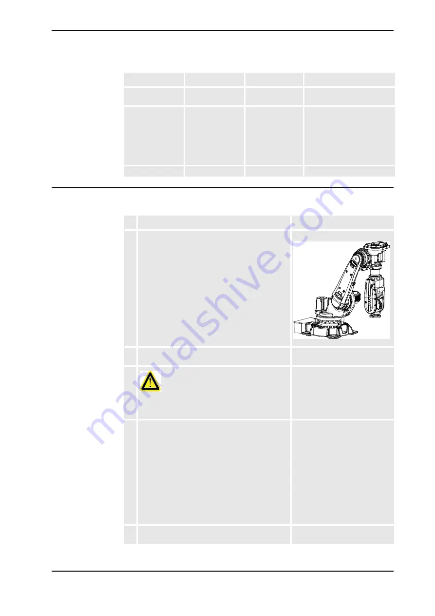
1. Move the robot to the position shown in the figure.
This is done in order to drain all oil from the gearbox
axis 3.
xx06000030414
2. Drain the oil from gearbox axis 3.
Detailed in section
.
3.
DANGER!
Turn off all electric power, hydraulic and pneumatic
pressure supplies to the robot!
4. Secure the robot from collapsing once the motor
axis 3 is removed, by following the procedure
detailed below:
•
Move the lower arm as far back as possible.
•
Release the brakes
on motor axis 2 and let
the lower arm rest on its mechanical stop.
•
Also
release the brakes
on motor axis 3 and
let the upper arm rest on its mechanical stop.
•
The lower and upper arms now rests on their
respective mechanical stops. The motor axis
3 can now be replaced without securing the
armsystem in an overhead crane.
Detailed in section
releasing the brakes on page 61
5. Remove any equipment hindering access to motor
axis 3.
Continued
Continues on next page


