


Page 74
© Copyright 2021 ABB. All rights reserved.
in a plant configured for
“
Centralized Architecture.
”
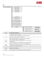
1.
Using a calibrated DVM, measure the plant load from the sense
connection points on the plant shunt(s).
2.
Calculate the plant load, in amperes, as measured by the DVM.
a.
Divide the mV DVM reading by the rated shunt mV value
b.
Multiply this result by the shunt ampere rating
This value is the plant load measured by the DVM, in amperes.
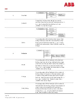
3.
Using the Meter Calibration Menus, reset the plant Plant Current reading by selecting RESET LOAD.
Press the Enter key to reset the load. This will remove any pre
-
existing user calibrated values if they
exist.
4.
Wait at least 5 seconds and press the ESCAPE key.
5.
Select CALIBRATE LOAD.
Use the Arrows, and UP/DOWN keys to
calibrate the system Load. Press ENTER to save.
NOTE:
The maximum total change is +/
-
10% of the
current load value
.
6.
Press the <ESCAPE> key until the default screen is displayed. Verify
that the plant current reading has been changed.
NOTE:
This operation is performed and verified ONLY if plant load is constant during the calibration procedure.
Observation:
•
Displayed System load changes to new value.
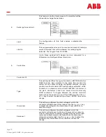
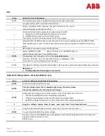
High Float Voltage Alarm –
New Installations only
Step
Action for Testing the High Float Voltage Alarm
NOTE:
Clear all controller alarms for this test.
NOTE:
The high voltage alarm test is completed by raising the plant voltage
above the threshold set for HFV (High Float Voltage) .
NOTE:
Raising the plant voltage on a working system is left to the discretion of the user.
•
This test could disrupt power to working equipment.
•
If the test is performed, verify that the plant is in FLOAT mode
•
Rectifier voltage has been set to the normal level after completing the test.
1.
Using the Voltage Alarms Menu Screens, note High Float Alarm threshold value.
2.
Using the Float Settings Menu Screens, select Set Point and note the value.
NOTE:
The next step WILL RAISE the system voltage.
3.
Use the Arrows, and UP/DOWN keys to change the system float voltage setpoint to 0.1V above the
High Float Alarm Threshold.. Press
ENTER to save.
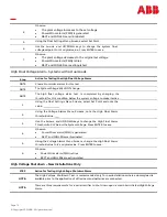
Step
Action for Current Calibration
NOTE:
The following procedure is applicable only in plants with Load shunts
Summary of Contents for GPS4827
Page 12: ...Page 12 Copyright 2021 ABB All rights reserved This page intentionally left blank ...
Page 20: ...Page 20 Copyright 2021 ABB All rights reserved This page intentionally left blank ...
Page 24: ...Page 24 Copyright 2021 ABB All rights reserved This page intentionally left blank ...
Page 30: ...Page 30 Copyright 2021 ABB All rights reserved This page intentionally left blank ...
Page 34: ...Page 34 Copyright 2021 ABB All rights reserved This page intentionally left blank ...
Page 62: ...Page 62 Copyright 2021 ABB All rights reserved Control and Operations Menu Map ...
Page 63: ...Page 63 Copyright 2021 ABB All rights reserved Status Menu Map ...
Page 64: ...Page 64 Copyright 2021 ABB All rights reserved History Menu Map Statistics Menu Map ...
Page 80: ...Page 80 Copyright 2021 ABB All rights reserved This page intentionally left blank ...
Page 82: ...Page 82 Copyright 2021 ABB All rights reserved This page intentionally left blank ...
Page 90: ...Page 90 Copyright 2021 ABB All rights reserved This page intentionally left blank ...


