


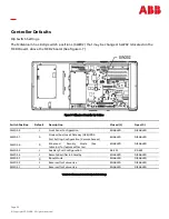


Page 41
© Copyright 2021 ABB. All rights reserved.
The user may connect a maximum of 95 of any combination of these modules serially.
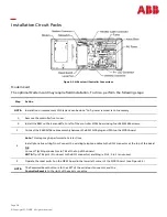
Step
Action
NOTE:
The Remote Peripheral Monitoring feature has been designed into the MCR1 board and requires no additional
circuit packs. Monitoring and control modules ARE required, based on the application.
NOTE:
This section only describes a
single module
connection to the controller. Modules MUST BE PROGRAMMED
after they have been installed or they may not function properly. Detailed connection and configuration
information may be found in the User
’
s Guide for Millennium II Controller Advanced Features manual.
1.
Using the RPM bus cable (Ordering Code 407377704), wrap the cable throughthe EMI inductor bead twice.
Place the bead approximately 3 inches from the end of the cable.
2.
Connect the bus cable to:
*connections of the bus wire are NOT polarity sensitive.
3.
Secure the module connection unit and route the wires through the open
-
faced bottom of the connection
unit.
4.
Make the connections to TB2 on the connection unit:
*connections of the bus wire are NOT polarity sensitive
.
*Connections of the bus wire are NOT Polarity Sensitive
* there are 2 IN, and 2 OUT connections. Either one may be used.
5.
Locate the control unit. This is the half with circuitry on it.
6.
In the lower right hand side of the control unit (inside), are two rotary switches. Set SW
-
1 (LO) to 1. The module
will be recognized as 01 by the controller. Other modules added cannot have the same address or 00 for the
address.
7.
Carefully attach the control unit to the connection unit using the ribbon connector.
NOTE:
This connector/cable is not keyed, so be careful to line up the pins properly.
8.
After approximately 1 minute, the green LED on the front of the module will blink once approximately every 5
seconds. Detailed troubleshooting information may be found in the User
’
s Guide for Millennium II Controller
Advanced Features manual.
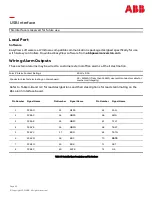
TB
-
1 Pin
Assignments
TP
-
1 Pin
Description
RPM Conductor Color
RPM Conductor Description
6
*6
Blue or White
Power /Communications
8
*8
Blue or White
Power /Communications
9 or 10
FGND
Blue or White
Shield
TB
-
2 Pin Assignments
RPM Conductor Color
RPM Conductor Description
IN
Blue or White
Power /Communications
OUT
Blue or White
Power /Communications
SHIELD
Bare Wire
Shield
Remote Peripheral Monitoring (RPM) (continued)
Summary of Contents for GPS4827
Page 12: ...Page 12 Copyright 2021 ABB All rights reserved This page intentionally left blank ...
Page 20: ...Page 20 Copyright 2021 ABB All rights reserved This page intentionally left blank ...
Page 24: ...Page 24 Copyright 2021 ABB All rights reserved This page intentionally left blank ...
Page 30: ...Page 30 Copyright 2021 ABB All rights reserved This page intentionally left blank ...
Page 34: ...Page 34 Copyright 2021 ABB All rights reserved This page intentionally left blank ...
Page 62: ...Page 62 Copyright 2021 ABB All rights reserved Control and Operations Menu Map ...
Page 63: ...Page 63 Copyright 2021 ABB All rights reserved Status Menu Map ...
Page 64: ...Page 64 Copyright 2021 ABB All rights reserved History Menu Map Statistics Menu Map ...
Page 80: ...Page 80 Copyright 2021 ABB All rights reserved This page intentionally left blank ...
Page 82: ...Page 82 Copyright 2021 ABB All rights reserved This page intentionally left blank ...
Page 90: ...Page 90 Copyright 2021 ABB All rights reserved This page intentionally left blank ...


