


26
GAA610-M
ADVANCED EMISSION GAS MONITORING SYSTEM | OI/GAA610-M-EN REV. B
… 6 Installation
… Probe tube and filter unit installation
Installation
Flange orientation
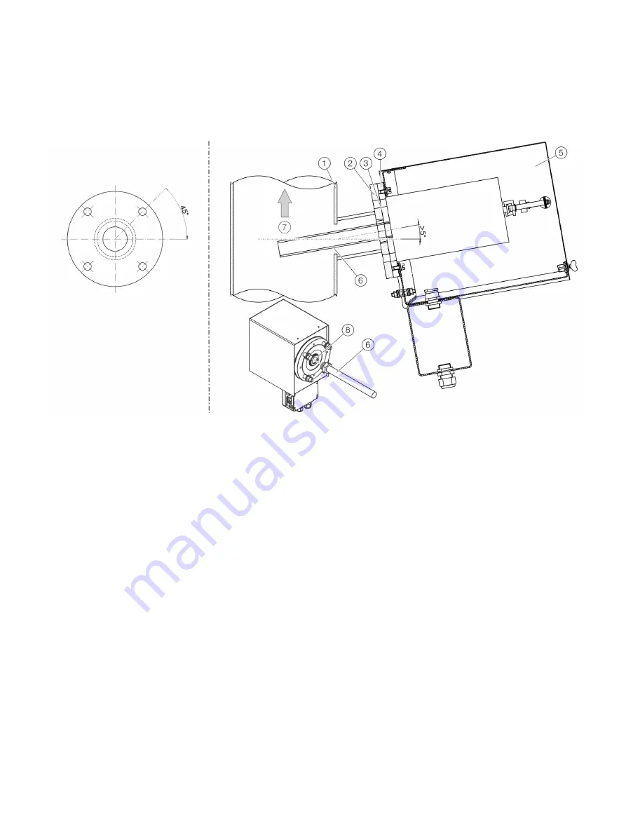
Filter unit
1
Duct wall
2
Flange
3
Flange gasket
4
Probe flange
5
Filter Unit
6
Probe tube
7
Flow direction
8
Sample gas inlet
Figure 12: Filter unit installation
1. Screw the probe tube
6
into the sample gas inlet
8
of the filter unit.
2. Insert the pre-assembled probe tube with filter unit in the wall tube and screw the flange of the filter unit to the flange of the wall
tube. Use the green seal from the accessories pack to seal the space between the flanges of wall tube and filter unit.
3. Mount the heating sleeve on the filter unit.
4. If applicable, install the compressed-air hoses between the filter unit and the back-purging unit.


