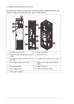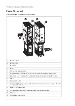
The figure below shows the components of the brake chopper cubicles with top entry and
exit of cables and shrouds removed.
Terminals for brake resistor cable connection
7
Control panel (J400)
1
Brake resistor fuses
8
Drive monitoring display (J401)
2
Cabinet fans
9
Brake chopper fuses
3
BCU-x2 control unit
10
Brake chopper module
4
Cabinet heater (G300)
11
Brake chopper cooling fan
5
Cable entries for brake resistor and control
cables
6
Operation principle and hardware description 17
Summary of Contents for ACS880-607 Series
Page 1: ... ABB INDUSTRIAL DRIVES ACS880 607 3 phase brake units Hardware manual ...
Page 2: ......
Page 4: ......
Page 8: ...8 ...
Page 12: ...12 ...
Page 30: ...30 ...
Page 32: ...32 ...
Page 36: ...36 ...
Page 44: ...44 ...
Page 54: ...54 ...
Page 62: ...62 ...
Page 66: ...66 Maintenance ...
Page 82: ...Dimension drawing bottom exit 82 Dimension drawings ...
Page 83: ...Dimension drawings 83 ...
Page 84: ...Dimension drawing top exit 84 Dimension drawings ...
Page 85: ... Dimension drawings 85 ...
Page 86: ......

