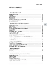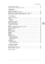
Minimizing electromagnetic interference ...................................................
Maximum cable length ........................................................................
Placing the brake resistors ......................................................................
Selecting the resistor thermal switch cable ...................................................
Protecting the system against thermal overload .............................................
Operation principle ............................................................................
Protecting the system against short-circuits ..................................................
Contents of this chapter ..........................................................................
Electrical safety precautions ....................................................................
General notes .....................................................................................
Static electricity ................................................................................
Optical components ...........................................................................
Checking the insulation of brake resistor and resistor cable ...............................
Connecting the brake resistor cables and thermal switch ..................................
Connection diagram ..........................................................................
Connection procedure of the resistor cables ..............................................
Connection procedure of the thermal switch cable .......................................
Connecting a PC ..................................................................................
Contents of this chapter ..........................................................................
BCU-x2 control unit layout and connections ..................................................
Default I/O diagram of the brake control unit .................................................
External power supply for the control unit (XPOW) ..........................................
The XD2D connector .............................................................................
Safe torque off (XSTO, XSTO OUT) ...........................................................
FSO-xx safety functions module connection (X12) ..........................................
SDHC memory card slot .........................................................................
Connector data ....................................................................................
BCU-x2 ground isolation diagram ...........................................................
Installation checklist of the drive
Contents of this chapter ..........................................................................
Contents of this chapter ..........................................................................
Start-up procedure ................................................................................
Start-up procedure ............................................................................
Contents of this chapter ..........................................................................
Control panel and panel platform/holder LEDs ...........................................
Control unit LEDs ..............................................................................
R8i module LEDs ..............................................................................
6 Table of contents
Summary of Contents for ACS880-607 Series
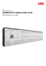
Page 1: ... ABB INDUSTRIAL DRIVES ACS880 607 3 phase brake units Hardware manual ...
Page 2: ......
Page 4: ......
Page 8: ...8 ...
Page 12: ...12 ...
Page 30: ...30 ...
Page 32: ...32 ...
Page 36: ...36 ...
Page 44: ...44 ...
Page 54: ...54 ...
Page 62: ...62 ...
Page 66: ...66 Maintenance ...
Page 82: ...Dimension drawing bottom exit 82 Dimension drawings ...
Page 83: ...Dimension drawings 83 ...
Page 84: ...Dimension drawing top exit 84 Dimension drawings ...
Page 85: ... Dimension drawings 85 ...
Page 86: ......

