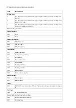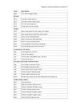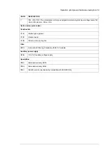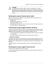
Connecting the brake resistor cables and thermal switch
■
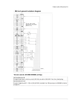
Connection diagram
This diagram shows the brake resistor cable connections and an example connection of
the thermal switches.
The diagram also shows the internal connections of the brake unit done by ABB.
9
:
8
'&
'&
3(
'&
'&
t
t
t
5
5
5
9
',
97
95
9
9
5
5
5
Brake chopper cubicle
1
DC switch/disconnector including charging circuit (+F286)
2
Control unit
3
Brake chopper module
4
Brake resistors
5
40 Electrical installation
Summary of Contents for ACS880-607 Series
Page 1: ... ABB INDUSTRIAL DRIVES ACS880 607 3 phase brake units Hardware manual ...
Page 2: ......
Page 4: ......
Page 8: ...8 ...
Page 12: ...12 ...
Page 30: ...30 ...
Page 32: ...32 ...
Page 36: ...36 ...
Page 44: ...44 ...
Page 54: ...54 ...
Page 62: ...62 ...
Page 66: ...66 Maintenance ...
Page 82: ...Dimension drawing bottom exit 82 Dimension drawings ...
Page 83: ...Dimension drawings 83 ...
Page 84: ...Dimension drawing top exit 84 Dimension drawings ...
Page 85: ... Dimension drawings 85 ...
Page 86: ......

