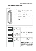
Brake chopper module connectors
■
Connectors X50…X53
Connector X50
Not in use.
9
115/230 V AC (50/60 Hz) input for optional heating element
(+C183).
Not in use in brake chopper modules.
N
8
L
7
Not in use.
6
115/230 V AC 50 Hz input for internal power supply (BDPS)
(115 V AC 60 Hz with G304).
N
5
L
4
400 V AC (50/60 Hz) supply for optional DOL (direct-online)
cooling fan (C188).
Note:
In modules wC188, the DOL wiring is present but not
in use.
W
3
V
2
U
1
Connectors X51, X52, X53
Not in use.
STO
OUT
X51
STO OUT
X51
FE
GND
24
V
GND
24
V
STO connectors of the mod-
ule. Must be connected to
24 V DC for the module to
start.
STO IN
X52
STO IN
X52
FE
GN
D
24
V
GN
D
24
V
24 V DC for BCU and for
STO IN to enable the mod-
ule operation.
24V OUT
X53
24V OUT
X53
FE
24
V
GN
D
24
V
GN
D
Note:
The Safe torque off (STO) safety function is only
implemented in inverter units. Therefore, the STO
function cannot be used in supply, rectifier, DC/DC
converter and brake units. In these units, de-ener-
gizing any connection of STO IN (X52) connector
stops the unit. Note that this stop is not safety re-
lated and must not be used for safety function
purposes.
Operation principle and hardware description 19
Summary of Contents for ACS880-607 Series
Page 1: ... ABB INDUSTRIAL DRIVES ACS880 607 3 phase brake units Hardware manual ...
Page 2: ......
Page 4: ......
Page 8: ...8 ...
Page 12: ...12 ...
Page 30: ...30 ...
Page 32: ...32 ...
Page 36: ...36 ...
Page 44: ...44 ...
Page 54: ...54 ...
Page 62: ...62 ...
Page 66: ...66 Maintenance ...
Page 82: ...Dimension drawing bottom exit 82 Dimension drawings ...
Page 83: ...Dimension drawings 83 ...
Page 84: ...Dimension drawing top exit 84 Dimension drawings ...
Page 85: ... Dimension drawings 85 ...
Page 86: ......

