
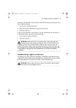


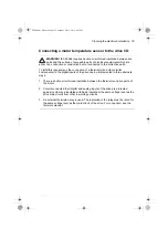


88 Electrical installation
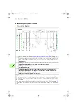
Connection procedure for frames R4 and R5
1. Remove the front cover. IP21 units: Release the retaining clip with a screwdriver
(a) and lift the cover from the bottom outwards (b).
2. For IP21 drives: Remove the cable entry box cover by undoing the mounting
screw.
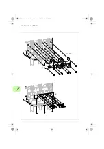
3. For frame R4: Remove the EMC shroud that separates the input and output
cabling if needed for earier installation.
4. Remove the shroud on the power cable terminals by releasing the clips and lifting
the shroud up from the sides with a screwdriver (a).
Knock out holes in the shroud
for the cables to be installed (b).
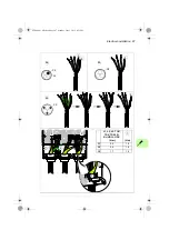
5. Attach the residual voltage warning sticker in the local language next to the
control unit top.
6. Cut adequate holes into the rubber grommets. Slide the grommets onto the
cables. Slide the cables through the holes of the bottom plate and attach the
grommets to the holes.
7. Prepare the ends of the input power and motor cables as illustrated in the figure.
Note
: Bare shield will be grounded 360 degrees under the grounding clamp.
8. Ground the cable shields 360 degrees under the grounding clamps.
9. Connect the twisted cable shields to the grounding terminals.
10. Connect the phase conductors of the input cable to the L1, L2 and L3 terminals
and the phase conductors of the motor cable to the T1/U, T2/V and T3/W
terminals. Tighten the screws to the torque given in the figure below.
Note for
frame R5:
For easier installation, the power cable terminals can be removed by
undoing their mounting nuts. Fasten the terminals back to their place by tightening
the mounting nuts.
11
ACS880-01 HW.book Page 88 Monday, July 1, 2013 4:51 PM
Summary of Contents for ACS880-01 Series
Page 4: ...ACS880 01 HW book Page 4 Monday July 1 2013 4 51 PM...
Page 12: ...12 ACS880 01 HW book Page 12 Monday July 1 2013 4 51 PM...
Page 20: ...20 Safety instructions ACS880 01 HW book Page 20 Monday July 1 2013 4 51 PM...
Page 26: ...26 Introduction to the manual ACS880 01 HW book Page 26 Monday July 1 2013 4 51 PM...
Page 80: ...80 Planning the electrical installation ACS880 01 HW book Page 80 Monday July 1 2013 4 51 PM...
Page 96: ...96 Electrical installation 8b R8 R9 ACS880 01 HW book Page 96 Monday July 1 2013 4 51 PM...
Page 98: ...98 Electrical installation 16 13 R8 R9 ACS880 01 HW book Page 98 Monday July 1 2013 4 51 PM...
Page 118: ...118 Start up ACS880 01 HW book Page 118 Monday July 1 2013 4 51 PM...
Page 120: ...120 Fault tracing ACS880 01 HW book Page 120 Monday July 1 2013 4 51 PM...
Page 131: ...Maintenance 131 3 4 5 3 ACS880 01 HW book Page 131 Monday July 1 2013 4 51 PM...
Page 172: ...172 Technical data ACS880 01 HW book Page 172 Monday July 1 2013 4 51 PM...
Page 196: ...196 Dimension drawings ACS880 01 HW book Page 196 Monday July 1 2013 4 51 PM...
Page 209: ...Safe Torque off function 209 Certificate ACS880 01 HW book Page 209 Monday July 1 2013 4 51 PM...
Page 210: ...210 Safe Torque off function ACS880 01 HW book Page 210 Monday July 1 2013 4 51 PM...
Page 220: ...220 Resistor braking ACS880 01 HW book Page 220 Monday July 1 2013 4 51 PM...


