


Planning the electrical installation 77
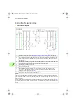
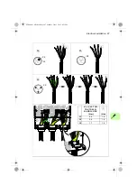
Switching the motor power supply from drive to direct-on-line
1. Stop the drive and the motor with the drive control panel (drive in local control
mode) or with the external stop signal (drive in remote control mode).
2. Open the main contactor of the drive with S11.
3. Switch the motor power supply from the drive to direct-on-line with S40.
4. Wait for 10 seconds to allow the motor magnetization to die away.
5. Start the motor with S41.
Switching the motor power supply from direct-on-line to drive
1. Stop the motor with S42.
2. Switch the motor power supply from direct-on-line to the drive with S40.
3. Close the main contactor of the drive with switch S11 (-> turn to position ST for
two seconds and leave at position 1).
4. Start the drive and the motor with the drive control panel (drive in local control
mode) or with the external start signal (drive in remote control mode).
Protecting the contacts of relay outputs
Inductive loads (relays, contactors, motors) cause voltage transients when switched
off.
The relay contacts on the drive control unit are protected with varistors (250 V)
against overvoltage peaks. In spite of this, it is highly recommended that inductive
loads are equipped with noise attenuating circuits (varistors, RC filters [AC] or diodes
[DC]) in order to minimize the EMC emission at switch-off. If not suppressed, the
disturbances may connect capacitively or inductively to other conductors in the
control cable and form a risk of malfunction in other parts of the system.
Install the protective component as close to the inductive load as possible. Do not
install protective components at the relay outputs.
ACS880-01 HW.book Page 77 Monday, July 1, 2013 4:51 PM
Summary of Contents for ACS880-01 Series
Page 4: ...ACS880 01 HW book Page 4 Monday July 1 2013 4 51 PM...
Page 12: ...12 ACS880 01 HW book Page 12 Monday July 1 2013 4 51 PM...
Page 20: ...20 Safety instructions ACS880 01 HW book Page 20 Monday July 1 2013 4 51 PM...
Page 26: ...26 Introduction to the manual ACS880 01 HW book Page 26 Monday July 1 2013 4 51 PM...
Page 80: ...80 Planning the electrical installation ACS880 01 HW book Page 80 Monday July 1 2013 4 51 PM...
Page 96: ...96 Electrical installation 8b R8 R9 ACS880 01 HW book Page 96 Monday July 1 2013 4 51 PM...
Page 98: ...98 Electrical installation 16 13 R8 R9 ACS880 01 HW book Page 98 Monday July 1 2013 4 51 PM...
Page 118: ...118 Start up ACS880 01 HW book Page 118 Monday July 1 2013 4 51 PM...
Page 120: ...120 Fault tracing ACS880 01 HW book Page 120 Monday July 1 2013 4 51 PM...
Page 131: ...Maintenance 131 3 4 5 3 ACS880 01 HW book Page 131 Monday July 1 2013 4 51 PM...
Page 172: ...172 Technical data ACS880 01 HW book Page 172 Monday July 1 2013 4 51 PM...
Page 196: ...196 Dimension drawings ACS880 01 HW book Page 196 Monday July 1 2013 4 51 PM...
Page 209: ...Safe Torque off function 209 Certificate ACS880 01 HW book Page 209 Monday July 1 2013 4 51 PM...
Page 210: ...210 Safe Torque off function ACS880 01 HW book Page 210 Monday July 1 2013 4 51 PM...
Page 220: ...220 Resistor braking ACS880 01 HW book Page 220 Monday July 1 2013 4 51 PM...


