


66 Planning the electrical installation
1)
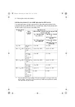
The cable sizing is based on max. 9 cables laid on a cable ladder side by side, three ladder
type trays one on top of the other, ambient temperature 30 °C, PVC insulation, surface
temperature 70 °C (EN 60204-1 and IEC 60364-5-52/2001). For other conditions, size the
cables according to local safety regulations, appropriate input voltage and the load current
of the drive. See also page
for the accepted cable sizes of the drive.
2)
The cable sizing is based on NEC Table 310-16 for copper wires, 75 °C (167 °F) wire
insulation at 40 °C (104 °F) ambient temperature. Not more than three current-carrying
conductors in raceway or cable or earth (directly buried). For other conditions, size the
cables according to local safety regulations, appropriate input voltage and the load current
of the drive. See also page
for the accepted cable sizes of the drive.
3)
The biggest cable size accepted by the connection terminals of frame R8 is 2 × (3×150).
Biggest possible cable size is 3x240 or 400 MCM if the terminal type is changed and the
cable entry box is not used.
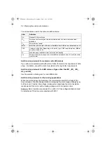
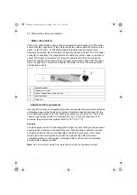
Alternative power cable types
The recommended and not allowed power cable types to be used with the drive are
presented below.
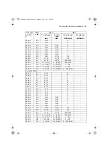
414A-5
R9
2 × (3×150)
2 × (3×240)
2 × 250 MCM
-
U
N
= 525…690 V
07A3-7
R5
3×1.5
-
14
12
09A8-7
R5
3×1.5
-
14
12
14A2-7
R5
3×2.5
-
14
12
018A-7
R5
3×4
-
12
10
022A-7
R5
3×6
-
10
8
026A-7
R5
3×10
3×25
8
6
035A-7
R5
3×10
3×25
8
6
042A-7
R5
3×16
3×25
6
4
049A-7
R5
3×16
3×25
6
4
061A-7
R6
3×25
3×35
4
3
084A-7
R6
3×35
3×50
3
2
098A-7
R7
3×50
3×70
2
1/0
119A-7
R7
3×70
3×95
1/0
3/0
142A-7
R8
3×95
3)
3×120
2/0
4/0
174A-7
R8
3×120
3)
2 × (3×70)
4/0
300
210A-7
R9
3×185
2 × (3×95)
300 MCM
2 × 3/0
271A-7
R9
3×240
2 × (3×120)
400 MCM
2 × 4/0
3AXD00000588487
Drive type
ACS880-
01-
Frame
size
IEC
1)
US
2)
Cu cable type
Al cable
type
Cu cable type
Al cable type
mm
2
mm
2
AWG/kcmil
AWG/kcmil
ACS880-01 HW.book Page 66 Monday, July 1, 2013 4:51 PM
Summary of Contents for ACS880-01 Series
Page 4: ...ACS880 01 HW book Page 4 Monday July 1 2013 4 51 PM...
Page 12: ...12 ACS880 01 HW book Page 12 Monday July 1 2013 4 51 PM...
Page 20: ...20 Safety instructions ACS880 01 HW book Page 20 Monday July 1 2013 4 51 PM...
Page 26: ...26 Introduction to the manual ACS880 01 HW book Page 26 Monday July 1 2013 4 51 PM...
Page 80: ...80 Planning the electrical installation ACS880 01 HW book Page 80 Monday July 1 2013 4 51 PM...
Page 96: ...96 Electrical installation 8b R8 R9 ACS880 01 HW book Page 96 Monday July 1 2013 4 51 PM...
Page 98: ...98 Electrical installation 16 13 R8 R9 ACS880 01 HW book Page 98 Monday July 1 2013 4 51 PM...
Page 118: ...118 Start up ACS880 01 HW book Page 118 Monday July 1 2013 4 51 PM...
Page 120: ...120 Fault tracing ACS880 01 HW book Page 120 Monday July 1 2013 4 51 PM...
Page 131: ...Maintenance 131 3 4 5 3 ACS880 01 HW book Page 131 Monday July 1 2013 4 51 PM...
Page 172: ...172 Technical data ACS880 01 HW book Page 172 Monday July 1 2013 4 51 PM...
Page 196: ...196 Dimension drawings ACS880 01 HW book Page 196 Monday July 1 2013 4 51 PM...
Page 209: ...Safe Torque off function 209 Certificate ACS880 01 HW book Page 209 Monday July 1 2013 4 51 PM...
Page 210: ...210 Safe Torque off function ACS880 01 HW book Page 210 Monday July 1 2013 4 51 PM...
Page 220: ...220 Resistor braking ACS880 01 HW book Page 220 Monday July 1 2013 4 51 PM...


