


212 Resistor braking
Note
: A custom resistor can be selected within the limits imposed by the internal
brake chopper of the drive:
•
The resistance value of the custom resistor is at least
R
min
. The braking power
capacity of the resistor can be calculated from the following equation:
WARNING!
Never use a brake resistor with a resistance below the
value specified for the particular drive / brake chopper / resistor
combination. The drive and the chopper are not able to handle the overcurrent
caused by the low resistance.
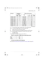
3. Check the resistor selection. The energy generated by the motor during a 400-
second period must not exceed the resistor heat dissipation capacity
E
R
.
Note
: If the
E
R
value is not sufficient, it is possible to use a four-resistor assembly in
which two standard resistors are connected in parallel, two in series. The
E
R
value of
the four-resistor assembly is four times the value specified for the standard resistor.
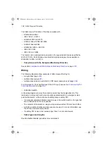
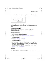
Selecting and routing the brake resistor cables
Use the same cable type for the resistor cabling as for the drive input cabling to
ensure that the input fuses also protect the resistor cable. Alternatively, a two
conductor shielded cable with the same cross-sectional area can be used.
where
P
max
Maximum power generated by the motor during braking
U
DC
Voltage over the resistor during braking.
U
DC
equals to
1.35 · 1.25 · 240 V DC (when supply voltage is 208 to 240 V AC)
1.35 · 1.25 · 415 V DC (when supply voltage is 380 to 415 V AC)
1.35 · 1.25 · 500 V DC (when supply voltage is 440 to 500 V AC) or
1.35 · 1.25 · 690 V DC (when supply voltage is 525 to 690 AC)
R
Resistor resistance (ohm)
P
max
<
U
DC
R
2
ACS880-01 HW.book Page 212 Monday, July 1, 2013 4:51 PM
Summary of Contents for ACS880-01 Series
Page 4: ...ACS880 01 HW book Page 4 Monday July 1 2013 4 51 PM...
Page 12: ...12 ACS880 01 HW book Page 12 Monday July 1 2013 4 51 PM...
Page 20: ...20 Safety instructions ACS880 01 HW book Page 20 Monday July 1 2013 4 51 PM...
Page 26: ...26 Introduction to the manual ACS880 01 HW book Page 26 Monday July 1 2013 4 51 PM...
Page 80: ...80 Planning the electrical installation ACS880 01 HW book Page 80 Monday July 1 2013 4 51 PM...
Page 96: ...96 Electrical installation 8b R8 R9 ACS880 01 HW book Page 96 Monday July 1 2013 4 51 PM...
Page 98: ...98 Electrical installation 16 13 R8 R9 ACS880 01 HW book Page 98 Monday July 1 2013 4 51 PM...
Page 118: ...118 Start up ACS880 01 HW book Page 118 Monday July 1 2013 4 51 PM...
Page 120: ...120 Fault tracing ACS880 01 HW book Page 120 Monday July 1 2013 4 51 PM...
Page 131: ...Maintenance 131 3 4 5 3 ACS880 01 HW book Page 131 Monday July 1 2013 4 51 PM...
Page 172: ...172 Technical data ACS880 01 HW book Page 172 Monday July 1 2013 4 51 PM...
Page 196: ...196 Dimension drawings ACS880 01 HW book Page 196 Monday July 1 2013 4 51 PM...
Page 209: ...Safe Torque off function 209 Certificate ACS880 01 HW book Page 209 Monday July 1 2013 4 51 PM...
Page 210: ...210 Safe Torque off function ACS880 01 HW book Page 210 Monday July 1 2013 4 51 PM...
Page 220: ...220 Resistor braking ACS880 01 HW book Page 220 Monday July 1 2013 4 51 PM...


