Maintenance
109
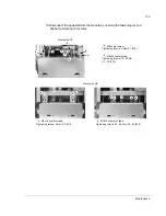
10.Disconnect the pedestal from the module by undoing the fastening (a) and
busbar connecting (b) screws.
b
b
b
Frame size R8
M10x25 combi screws
Tightening torque: 30...44 Nm (22...32 lbf ft)
b
b b
b
b
b
a
a
M6x16 combi screws
Tightening torque: 5 Nm (3.7 lbf ft)
a
M6 combi screw
Tightening torque: 5 Nm (3.7 lbf ft)
M8x25 combi screw
Tightening torque: 15...22 Nm
(11...16 lbf ft)
a
b
Frame size R7
b
b
a
a
a
a
a
a
b
Summary of Contents for ACS800-U7
Page 1: ...ACS800 Hardware Manual ACS800 07 Drives 45 to 560 kW ACS800 U7 Drives 50 to 600 hp ...
Page 4: ......
Page 28: ...Operation principle and hardware description 28 ...
Page 51: ...Planning the electrical installation 51 ...
Page 60: ...Planning the electrical installation 60 ...
Page 76: ...Electrical installation 76 ...
Page 84: ...Motor control and I O board RMIO 84 ...
Page 112: ...Maintenance 112 ...
Page 138: ...Dimensional drawings 138 Frame sizes R5 and R6 64778340_1 5 K ...
Page 139: ...Dimensional drawings 139 Frame sizes R7 and R8 68749930_1 7 C ...
Page 140: ...Dimensional drawings 140 IP54 and IP54R units of frame sizes R7 and R8 68749930_6 6 C ...
Page 148: ...3AFE64702165 Rev H EN 2012 09 19 Contact us www abb com drives www abb com drivespartners ...


