Mechanical installation
33
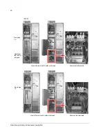
Fastening the cabinet with the outside brackets
Insert the bracket into the longitudinal hole in the edge of the cabinet frame body and
fasten it with a bolt to the floor.
Fastening bolt: M10 to M12 (3/8” to 1/2”).
Cubicle
width
mm [in.]
Fastening hole distance in mm [in.]
200 [7.87]
400 [15.75]
a: 250 [9.84]
600 [23.62]
a: 450 [17.71]
800 [31.50]
a: 650 [25.29]
1000 [39.37] a: 350 [13.78], b: 150 [5.91], a: 350 [13.78]
1200 [47.24] a: 450 [17.71], b: 150 [5.91], a: 450 [17.71]
a
b
a
46 [1.81]
Dimensions of the fastening bracket:
Cabinet frame body
Cabinet frame body
Summary of Contents for ACS800-U7
Page 1: ...ACS800 Hardware Manual ACS800 07 Drives 45 to 560 kW ACS800 U7 Drives 50 to 600 hp ...
Page 4: ......
Page 28: ...Operation principle and hardware description 28 ...
Page 51: ...Planning the electrical installation 51 ...
Page 60: ...Planning the electrical installation 60 ...
Page 76: ...Electrical installation 76 ...
Page 84: ...Motor control and I O board RMIO 84 ...
Page 112: ...Maintenance 112 ...
Page 138: ...Dimensional drawings 138 Frame sizes R5 and R6 64778340_1 5 K ...
Page 139: ...Dimensional drawings 139 Frame sizes R7 and R8 68749930_1 7 C ...
Page 140: ...Dimensional drawings 140 IP54 and IP54R units of frame sizes R7 and R8 68749930_6 6 C ...
Page 148: ...3AFE64702165 Rev H EN 2012 09 19 Contact us www abb com drives www abb com drivespartners ...


