Maintenance
106
Replacing the drive module (R5 and R6)
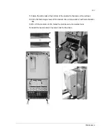
1. Open the swing-out frame. Undo screw (1) to open the swing-out frame wide.
2. Disconnect the control panel cable.
3. Disconnect the fan wires (detachable terminal).
4. Undo the fastening screws of the air baffle and fan cassette, and pull the air baffle
out.
5. Pull the fan cassette out.
6. Remove the shroud at the top of the module by undoing the fastening screws.
7. Remove the shrouds in the lower part of the cabinet.
8. Remove the additional fan (if any). See
Replacing the additional fan at the lower
part of the cubicle (R6 with du/dt filter, +E205)
on page
98
.
9. Disconnect the control cables by detaching the RMIO board terminals.
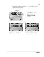
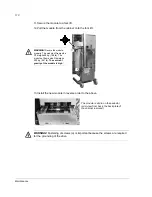
10.Disconnect the power busbars and cables.
Note
: Drives with safety functions (oQ963, Q964, +Q965, +Q966 or
+Q968): Disconnect the STO cable from the module.
5
4
3
4
4
6
6
4
2
1
10
10
10
10
10
10 10 10 10 10
10
10 10
Summary of Contents for ACS800-U7
Page 1: ...ACS800 Hardware Manual ACS800 07 Drives 45 to 560 kW ACS800 U7 Drives 50 to 600 hp ...
Page 4: ......
Page 28: ...Operation principle and hardware description 28 ...
Page 51: ...Planning the electrical installation 51 ...
Page 60: ...Planning the electrical installation 60 ...
Page 76: ...Electrical installation 76 ...
Page 84: ...Motor control and I O board RMIO 84 ...
Page 112: ...Maintenance 112 ...
Page 138: ...Dimensional drawings 138 Frame sizes R5 and R6 64778340_1 5 K ...
Page 139: ...Dimensional drawings 139 Frame sizes R7 and R8 68749930_1 7 C ...
Page 140: ...Dimensional drawings 140 IP54 and IP54R units of frame sizes R7 and R8 68749930_6 6 C ...
Page 148: ...3AFE64702165 Rev H EN 2012 09 19 Contact us www abb com drives www abb com drivespartners ...


