


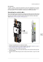


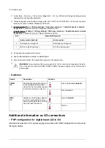

Connecting a PC
WARNING!
Do not connect the PC directly to the control panel connector of the control unit
as this can cause damage.
A PC (with eg, the Drive composer PC tool) can be connected as follows:
1.
Connect an ACx-AP-x control panel to the unit either
•
by inserting the control panel into the panel holder or platform, or
•
by using an Ethernet (eg, Cat 5e) networking cable.
2.
Remove the USB connector cover on the front of the control panel.
3.
Connect an USB cable (Type A to Type Mini-B) between the USB connector on the
control panel (3a) and a free USB port on the PC (3b).
4.
The panel will display an indication whenever the connection is active.
5.
See the documentation of the PC tool for setup instructions.
?
Start
Stop
Loc/Rem
?
Start
Stop
Loc/Rem
USB connected
3a
4
3b
2
2
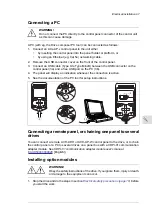
Connecting a remote panel, or chaining one panel to several
drives
You can connect a remote ACH-AP-H or ACH-AP-W control panel to the drive, or to chain
the control panel or a PC to several drives on a panel bus with a CDPI-01 communication
adapter module. See
CDPI-01 communication adapter module user's manual
[English]).
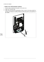
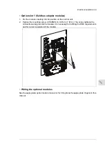
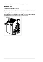
Installing option modules
WARNING!
Obey the safety instructions of the drive. If you ignore them, injury or death,
or damage to the equipment can occur.
1.
Stop the drive and do the steps in section
Electrical safety precautions (page 18)
before
you start the work.
Electrical installation 97
11
Summary of Contents for ACH580-04
Page 1: ... ABB DRIVES FOR HVAC ACH580 04 drive modules Hardware manual ...
Page 2: ......
Page 4: ......
Page 54: ...54 ...
Page 88: ...88 ...
Page 100: ...100 ...
Page 118: ...118 ...
Page 122: ...122 ...
Page 124: ...124 ...
Page 128: ...3 6 5 5 128 Maintenance ...
Page 134: ...134 ...
Page 156: ...R10 standard configuration 156 Dimension drawings ...
Page 157: ...R10 with E208 0H354 H356 H370 0H371 Dimension drawings 157 ...
Page 158: ...R10 with option B051 158 Dimension drawings ...
Page 159: ...R10 with option E208 H356 P906 192 Tools R10 3 1 Dimension drawings 159 ...
Page 160: ...R10 with option E208 0H371 H356 0H354 H370 P906 Tools 191 R10 2 1 160 Dimension drawings ...
Page 161: ...R10 with option B051 P906 190 Tools R10 1 1 Dimension drawings 161 ...
Page 162: ...R11 standard configuration 162 Dimension drawings ...
Page 163: ...R11 with option E208 0H371 H356 0H354 H370 Dimension drawings 163 ...
Page 164: ...R11 with option B051 164 Dimension drawings ...
Page 165: ...R11 with option E208 H356 P906 Dimension drawings 165 ...
Page 166: ...R11 with option E208 0H371 H356 0H354 H370 P906 166 Dimension drawings ...
Page 167: ...R11 with option B051 P906 Dimension drawings 167 ...
Page 186: ... Declaration of conformity 186 The Safe torque off function ...
Page 206: ...Dimension drawing 206 External control unit option P906 ...
Page 212: ...212 ...
Page 224: ...224 ...
Page 226: ...226 ...
Page 234: ...234 ...


