


General safety in installation, start-up and maintenance
These instructions are for all personnel who do work on the drive.
WARNING!
Obey these instructions. If you ignore them, injury or death, or damage to the
equipment can occur.
•
Keep the drive in its package until you install it. After unpacking, protect the drive from
dust, debris and moisture.
•
Use the required personal protective equipment: safety shoes with metal toe cap, safety
glasses, protective gloves and long sleeves, etc. Some parts have sharp edges.
•
Lift a heavy drive with a lifting device. Use the designated lifting points. See the dimension
drawings.
•
Incorrect lifting can cause danger or damage. Obey the local laws and regulations
applicable to lifting, such as requirements for planning the lift, for capacity and condition
of lifting equipment, and for training of personnel.
•
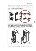
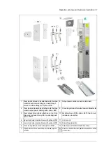
Attach the drive cabinet to the floor to prevent it from toppling over. The cabinet has a
high center of gravity. When you pull out heavy components or power modules, there
is a risk of overturning. Attach the cabinet also to the wall when necessary.
•
Do not use the module extraction/installation ramp with plinth heights which exceeds
the maximum allowed height. See the technical data.
•
Attach the module extraction/installation ramp carefully.
16 Safety instructions
3
Summary of Contents for ACH580-04
Page 1: ... ABB DRIVES FOR HVAC ACH580 04 drive modules Hardware manual ...
Page 2: ......
Page 4: ......
Page 54: ...54 ...
Page 88: ...88 ...
Page 100: ...100 ...
Page 118: ...118 ...
Page 122: ...122 ...
Page 124: ...124 ...
Page 128: ...3 6 5 5 128 Maintenance ...
Page 134: ...134 ...
Page 156: ...R10 standard configuration 156 Dimension drawings ...
Page 157: ...R10 with E208 0H354 H356 H370 0H371 Dimension drawings 157 ...
Page 158: ...R10 with option B051 158 Dimension drawings ...
Page 159: ...R10 with option E208 H356 P906 192 Tools R10 3 1 Dimension drawings 159 ...
Page 160: ...R10 with option E208 0H371 H356 0H354 H370 P906 Tools 191 R10 2 1 160 Dimension drawings ...
Page 161: ...R10 with option B051 P906 190 Tools R10 1 1 Dimension drawings 161 ...
Page 162: ...R11 standard configuration 162 Dimension drawings ...
Page 163: ...R11 with option E208 0H371 H356 0H354 H370 Dimension drawings 163 ...
Page 164: ...R11 with option B051 164 Dimension drawings ...
Page 165: ...R11 with option E208 H356 P906 Dimension drawings 165 ...
Page 166: ...R11 with option E208 0H371 H356 0H354 H370 P906 166 Dimension drawings ...
Page 167: ...R11 with option B051 P906 Dimension drawings 167 ...
Page 186: ... Declaration of conformity 186 The Safe torque off function ...
Page 206: ...Dimension drawing 206 External control unit option P906 ...
Page 212: ...212 ...
Page 224: ...224 ...
Page 226: ...226 ...
Page 234: ...234 ...


