


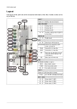
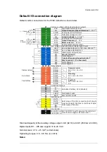


■
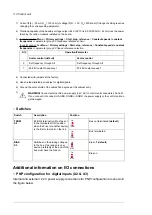
AI1 and AI2 as Pt100, Pt1000, Ni1000, KTY83 and KTY84 sensor inputs
(X1)
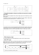
Sensors for motor temperature measurement can be connected between an analog input
and output, an example connection is shown below. Leave the other end of the shield
unconnected or ground it indirectly via a few nanofarads high-frequency capacitor, for
example, 3.3 nF / 630 V. The shield can also be grounded directly at both ends if they are
in the same ground line with no significant voltage drop between the end points.
...
AI1
AGND
AO1
AGND
2
1
3
T
T
T
One, two or three Pt100 sensors; one, two or three Pt1000 sensors; or one Ni1000, KTY83 or KTY84
sensor
1
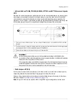
Set the input type to voltage for analog input AI1 or analog input AI2 with parameters. Set the appropriate
analog input unit to V (volt) in parameter group
12 Standard AI
.
2
Select the excitation mode in parameter group
13 Standard AO
.
3
WARNING!
As the inputs pictured above are not insulated according to IEC 60664, the
connection of the motor temperature sensor requires double or reinforced insulation
between motor live parts and the sensor.
If the assembly does not fulfill this requirement, the I/O board terminals must be
protected against contact and must not be connected to other equipment or the
temperature sensor must be isolated from the I/O terminals.
■
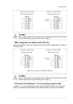
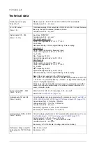
Safe torque off (X4)
For the drive to start, both connections (+24 V DC to IN1 and +24 V DC to IN2) must be
closed. By default, the terminal block has jumpers to close the circuit.
Remove the jumpers before connecting an external Safe torque off circuitry to the drive.
See also chapter
The Safe torque off function (page 171)
Note:
Only 24 V DC can be used for STO. Only PNP input configuration can be used.
Control unit 113
Summary of Contents for ACH580-04
Page 1: ... ABB DRIVES FOR HVAC ACH580 04 drive modules Hardware manual ...
Page 2: ......
Page 4: ......
Page 54: ...54 ...
Page 88: ...88 ...
Page 100: ...100 ...
Page 118: ...118 ...
Page 122: ...122 ...
Page 124: ...124 ...
Page 128: ...3 6 5 5 128 Maintenance ...
Page 134: ...134 ...
Page 156: ...R10 standard configuration 156 Dimension drawings ...
Page 157: ...R10 with E208 0H354 H356 H370 0H371 Dimension drawings 157 ...
Page 158: ...R10 with option B051 158 Dimension drawings ...
Page 159: ...R10 with option E208 H356 P906 192 Tools R10 3 1 Dimension drawings 159 ...
Page 160: ...R10 with option E208 0H371 H356 0H354 H370 P906 Tools 191 R10 2 1 160 Dimension drawings ...
Page 161: ...R10 with option B051 P906 190 Tools R10 1 1 Dimension drawings 161 ...
Page 162: ...R11 standard configuration 162 Dimension drawings ...
Page 163: ...R11 with option E208 0H371 H356 0H354 H370 Dimension drawings 163 ...
Page 164: ...R11 with option B051 164 Dimension drawings ...
Page 165: ...R11 with option E208 H356 P906 Dimension drawings 165 ...
Page 166: ...R11 with option E208 0H371 H356 0H354 H370 P906 166 Dimension drawings ...
Page 167: ...R11 with option B051 P906 Dimension drawings 167 ...
Page 186: ... Declaration of conformity 186 The Safe torque off function ...
Page 206: ...Dimension drawing 206 External control unit option P906 ...
Page 212: ...212 ...
Page 224: ...224 ...
Page 226: ...226 ...
Page 234: ...234 ...


