


•
gratings that guide air flow at the air inlet and outlet
•
air inlet and outlet at different sides of the cabinet
•
cool air inlet in the lower part of the front door, and an extra exhaust fan on the roof of
the cabinet.
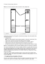
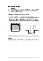
Prevent hot air circulation inside the cabinet with, for example, leak-proof air baffles. No
gaskets are usually required.
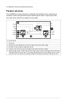
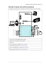
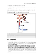
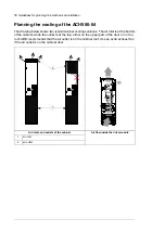
The drawing below shows the air flow inside and outside the cabinet.
Air flow in
1
Power module
2
Hot air circulation to be prevented
3
Air flow out
4
EMC requirements
Note the following when you plan the electromagnetic compatibility of the cabinet:
•
Generally, the fewer and smaller the holes in the cabinet, the better the interference
attenuation. The maximum recommended diameter of a hole in galvanic metal contact
in the covering cabinet structure is 100 mm (3.94 in). Pay special attention to the cooling
air inlet and outlet gratings.
•
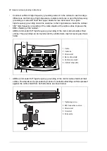
The best galvanic connection between the steel panels is achieved by welding them
together as no holes are necessary. If welding is not possible, ABB recommends to
leave the seams between the panels
unpainted
and equipped with special conductive
EMC strips to provide adequate galvanic connection. Usually, reliable strips are made
of flexible silicon mass covered with a metal mesh. The non-tightened touch-contact of
the metal surfaces is not sufficient, so a conductive gasket between the surfaces is
required. The maximum recommended distance between assembly screws is 100 mm
(3.94 in).
Generic cabinet planning instructions 41
Summary of Contents for ACH580-04
Page 1: ... ABB DRIVES FOR HVAC ACH580 04 drive modules Hardware manual ...
Page 2: ......
Page 4: ......
Page 54: ...54 ...
Page 88: ...88 ...
Page 100: ...100 ...
Page 118: ...118 ...
Page 122: ...122 ...
Page 124: ...124 ...
Page 128: ...3 6 5 5 128 Maintenance ...
Page 134: ...134 ...
Page 156: ...R10 standard configuration 156 Dimension drawings ...
Page 157: ...R10 with E208 0H354 H356 H370 0H371 Dimension drawings 157 ...
Page 158: ...R10 with option B051 158 Dimension drawings ...
Page 159: ...R10 with option E208 H356 P906 192 Tools R10 3 1 Dimension drawings 159 ...
Page 160: ...R10 with option E208 0H371 H356 0H354 H370 P906 Tools 191 R10 2 1 160 Dimension drawings ...
Page 161: ...R10 with option B051 P906 190 Tools R10 1 1 Dimension drawings 161 ...
Page 162: ...R11 standard configuration 162 Dimension drawings ...
Page 163: ...R11 with option E208 0H371 H356 0H354 H370 Dimension drawings 163 ...
Page 164: ...R11 with option B051 164 Dimension drawings ...
Page 165: ...R11 with option E208 H356 P906 Dimension drawings 165 ...
Page 166: ...R11 with option E208 0H371 H356 0H354 H370 P906 166 Dimension drawings ...
Page 167: ...R11 with option B051 P906 Dimension drawings 167 ...
Page 186: ... Declaration of conformity 186 The Safe torque off function ...
Page 206: ...Dimension drawing 206 External control unit option P906 ...
Page 212: ...212 ...
Page 224: ...224 ...
Page 226: ...226 ...
Page 234: ...234 ...


