


Mechanical installation
■
Necessary tools
•
Screwdriver and a set of suitable bits.
■
Unpacking and examining the delivery
1.
Open the option package. Make sure that the package contains:
•
the option module
•
a mounting screw.
2.
Make sure that there are no signs of damage.
■
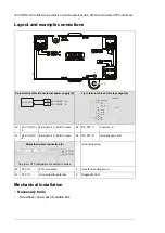
Installing the module
See section
Installing option modules (page 97)
Electrical installation
WARNING!
Obey the instructions in chapter
. If you ignore them,
injury or death, or damage to the equipment can occur. If you are not a qualified
electrician, do not do electrical work.
Make sure that the drive is disconnected from the input power during
installation. If the drive is already connected to the input power, wait for
5 minutes after disconnecting the input power.
■
Necessary tools
•
Screwdriver and a set of suitable bits.
■
Wiring
Connect the external control cables to the applicable module terminals. Ground the outer
shield of the cables 360 degrees under a grounding clamp on the grounding shelf of the
control cables.
Start-up
■
Setting the parameters
1.
Power up the drive.
2.
If no warning is shown,
•
make sure that the value of both parameters
15.01 Extension module type
and
15.02 Detected extension module
is CHDI-01.
If warning A7AB
Extension I/O configuration failure
is shown,
•
make sure that the value of parameter
15.02
is CHDI-01.
•
set parameter
15.01
value to CHDI-01.
You can now see the parameters of the extension module in parameter group
15 I/O
extension module
.
3.
Set the parameters of the extension module to applicable values.
CHDI-01 115/230 V digital input extension module 209
Summary of Contents for ACH580-04
Page 1: ... ABB DRIVES FOR HVAC ACH580 04 drive modules Hardware manual ...
Page 2: ......
Page 4: ......
Page 54: ...54 ...
Page 88: ...88 ...
Page 100: ...100 ...
Page 118: ...118 ...
Page 122: ...122 ...
Page 124: ...124 ...
Page 128: ...3 6 5 5 128 Maintenance ...
Page 134: ...134 ...
Page 156: ...R10 standard configuration 156 Dimension drawings ...
Page 157: ...R10 with E208 0H354 H356 H370 0H371 Dimension drawings 157 ...
Page 158: ...R10 with option B051 158 Dimension drawings ...
Page 159: ...R10 with option E208 H356 P906 192 Tools R10 3 1 Dimension drawings 159 ...
Page 160: ...R10 with option E208 0H371 H356 0H354 H370 P906 Tools 191 R10 2 1 160 Dimension drawings ...
Page 161: ...R10 with option B051 P906 190 Tools R10 1 1 Dimension drawings 161 ...
Page 162: ...R11 standard configuration 162 Dimension drawings ...
Page 163: ...R11 with option E208 0H371 H356 0H354 H370 Dimension drawings 163 ...
Page 164: ...R11 with option B051 164 Dimension drawings ...
Page 165: ...R11 with option E208 H356 P906 Dimension drawings 165 ...
Page 166: ...R11 with option E208 0H371 H356 0H354 H370 P906 166 Dimension drawings ...
Page 167: ...R11 with option B051 P906 Dimension drawings 167 ...
Page 186: ... Declaration of conformity 186 The Safe torque off function ...
Page 206: ...Dimension drawing 206 External control unit option P906 ...
Page 212: ...212 ...
Page 224: ...224 ...
Page 226: ...226 ...
Page 234: ...234 ...


