


Overall flowchart of the installation process
For instructions, see
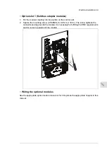
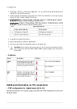
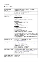
Task
Step
•
Installing the drive module into a cabin-
et (page 103)
• Installation drawings
Install the Rittal parts, drive bottom guide plate
and loose drive options in the drive module cu-
bicle.
1
• The component manufacturer’s instructions
•
Planning the cooling of the ACH580-
04 (page 50)
•
•
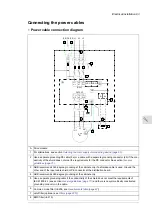
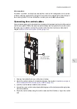
Connecting the power cables and installing the
shrouds (page 104)
Install the auxiliary components (such as mount-
ing plates, air baffles, switches, busbars etc.).
2
Attach the drive module to the cabinet
Connect the power cables and install the clear
plastic shrouds to the drive module.
•
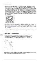
Connecting the control cables (page 95)
.
Connect the control cables.
3
• The component manufacturer’s instructions.
•
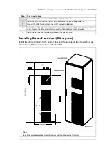
Installing the roof and door (Rittal
parts) (page 105)
Install the remaining parts, for example, cabinet
doors, side plates, etc.
4
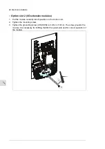
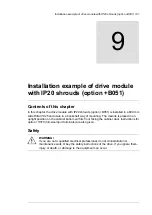
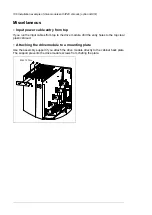
Installing the drive module into a cabinet
See appendix
Step-by-step drawings for an installation example of a drive module with the
+B051 option in a Rittal VX25 600 mm wide enclosure (page 235)
and the quick installation
guide.
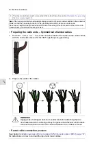
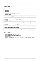
•
Install the punched section to the back of the cabinet frame.
•
Install the support rails and pedestal guide plate to the cabinet bottom frame.
•
Install the telescopic extraction/installation ramp to the pedestal guide plate.
•
B051: Remove the sheeting from the clear plastic shrouds from both sides.
•
H370: Install the top metallic shroud to the drive module.
•
B051:Install the back shrouds to the drive module.
•
To prevent the drive module from falling, attach its lifting lugs with chains to the cabinet
frame.
•
Push the drive module carefully into the cabinet along the telescopic extraction/installation
ramp.
•
Remove the ramp.
•
Attach the drive module to the pedestal guide plate.
•
Attach the drive module from top to the punched section at the cabinet back.
Note:
The fastening bracket grounds the drive module to the cabinet frame.
•
Install the air baffles. For B051, see chapter
and
Air baffles for the drive module with option
. For standard drive module configuration, see section
module configuration (page 51)
Installation example of drive module with IP20 shrouds (B051) 103
Summary of Contents for ACH580-04
Page 1: ... ABB DRIVES FOR HVAC ACH580 04 drive modules Hardware manual ...
Page 2: ......
Page 4: ......
Page 54: ...54 ...
Page 88: ...88 ...
Page 100: ...100 ...
Page 118: ...118 ...
Page 122: ...122 ...
Page 124: ...124 ...
Page 128: ...3 6 5 5 128 Maintenance ...
Page 134: ...134 ...
Page 156: ...R10 standard configuration 156 Dimension drawings ...
Page 157: ...R10 with E208 0H354 H356 H370 0H371 Dimension drawings 157 ...
Page 158: ...R10 with option B051 158 Dimension drawings ...
Page 159: ...R10 with option E208 H356 P906 192 Tools R10 3 1 Dimension drawings 159 ...
Page 160: ...R10 with option E208 0H371 H356 0H354 H370 P906 Tools 191 R10 2 1 160 Dimension drawings ...
Page 161: ...R10 with option B051 P906 190 Tools R10 1 1 Dimension drawings 161 ...
Page 162: ...R11 standard configuration 162 Dimension drawings ...
Page 163: ...R11 with option E208 0H371 H356 0H354 H370 Dimension drawings 163 ...
Page 164: ...R11 with option B051 164 Dimension drawings ...
Page 165: ...R11 with option E208 H356 P906 Dimension drawings 165 ...
Page 166: ...R11 with option E208 0H371 H356 0H354 H370 P906 166 Dimension drawings ...
Page 167: ...R11 with option B051 P906 Dimension drawings 167 ...
Page 186: ... Declaration of conformity 186 The Safe torque off function ...
Page 206: ...Dimension drawing 206 External control unit option P906 ...
Page 212: ...212 ...
Page 224: ...224 ...
Page 226: ...226 ...
Page 234: ...234 ...


