


4.
Connect the ground connection at the drive module end.
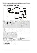
Maintenance
With the external control unit P906, the drive module removal procedure differs
slightly from the instructions given in chapter
Maintenance
: before you detach the drive
module, you must disconnect the control unit cables from the drive module in the following
way:
1.
Remove the middle front cover of the drive module to be able to disconnect the cables.
2 × combi screws M4×8 T20, 2 N·m (18 lbf·in).
2.
Disconnect the optical, 2 × STO, 24 V, and ground connections from the drive module,
and carefully remove the cables from the drive.
3.
Wind the cables so they will not be damaged as the drive module is removed.
4.
Continue the drive module removal procedure as described in chapter
Maintenance
.
External control unit (P906) 205
Summary of Contents for ACH580-04
Page 1: ... ABB DRIVES FOR HVAC ACH580 04 drive modules Hardware manual ...
Page 2: ......
Page 4: ......
Page 54: ...54 ...
Page 88: ...88 ...
Page 100: ...100 ...
Page 118: ...118 ...
Page 122: ...122 ...
Page 124: ...124 ...
Page 128: ...3 6 5 5 128 Maintenance ...
Page 134: ...134 ...
Page 156: ...R10 standard configuration 156 Dimension drawings ...
Page 157: ...R10 with E208 0H354 H356 H370 0H371 Dimension drawings 157 ...
Page 158: ...R10 with option B051 158 Dimension drawings ...
Page 159: ...R10 with option E208 H356 P906 192 Tools R10 3 1 Dimension drawings 159 ...
Page 160: ...R10 with option E208 0H371 H356 0H354 H370 P906 Tools 191 R10 2 1 160 Dimension drawings ...
Page 161: ...R10 with option B051 P906 190 Tools R10 1 1 Dimension drawings 161 ...
Page 162: ...R11 standard configuration 162 Dimension drawings ...
Page 163: ...R11 with option E208 0H371 H356 0H354 H370 Dimension drawings 163 ...
Page 164: ...R11 with option B051 164 Dimension drawings ...
Page 165: ...R11 with option E208 H356 P906 Dimension drawings 165 ...
Page 166: ...R11 with option E208 0H371 H356 0H354 H370 P906 166 Dimension drawings ...
Page 167: ...R11 with option B051 P906 Dimension drawings 167 ...
Page 186: ... Declaration of conformity 186 The Safe torque off function ...
Page 206: ...Dimension drawing 206 External control unit option P906 ...
Page 212: ...212 ...
Page 224: ...224 ...
Page 226: ...226 ...
Page 234: ...234 ...


