Section 4 Commissioning of PROFIBUS equipment Installing the PROFIBUS DP/PA Linking Device
3BDS009029R5001 B
101
9.
Connect the power pack.
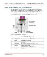
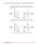
10. Each PROFIBUS PA segment must be terminated at the end of the line. The
terminating resistance required for the Linking Device LD 800P is already
integrated into the power link modules PL 810 and PL 890.
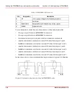
11. The PROFIBUS PA cable shield must be grounded for reasons of EMC
protection. This is possible in 2 ways:
–
Hard grounding at both ends of the PROFIBUS PA transmission line. This
requires laying a potential compensation line.
–
Hard grounding on all field devices, potential compensation in the field,
capacitive grounding on the Linking Device.
12. If the LD 800P is used, independently of whether or not it is a manufacturer
specific or profile GSD, always use the DP-GSD. Some PROFIBUS PA field
device manufacturers do not offer
any
PROFIBUS DP-GSDs. In this case, the
existing PROFIBUS PA-GSD must be converted by using the LD 800P convert
tool. The task of this conversion software is exclusively to enter the missing
transfer rate and set specific bus parameters to values that allow for problem-
free operation of the PROFIBUS DP.
The watch dog time T
WD
is set within the LD 800P to a default value of 5 sec.
This setting leads to a 5 sec. watchdog time of all underlying PA slave devices
independent of the T
WD
settings within the PROFIBUS DP master. If a watchdog
time adjustment of is not possible for the individual PA slave device there is a
possibility to use a service tool and a serial connection to adjust the watchdog
time for all PA slave devices within LD 800P.
Summary of Contents for AC 800M
Page 2: ......
Page 3: ...AC 800M PROFIBUS DP Installation System Version 5 0 5 1...
Page 8: ...Table of Contents 8 3BDS009029R5001 B...
Page 16: ...Released User Manuals and Release Notes About This User Manual 16 3BDS009029R5001 B...
Page 116: ...Updates in Revision Index B 116 3BDS009029R5001 B...
Page 117: ......

