


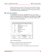


Section 2 Transmission Technology
Fibre optics cable type and speed
3BDS009029R5001 B
43
shows the different cable types, wave lengths and maximum distances,
reachable with the certain fibre media.
The path attenuation per km or meter is derived from the difference between the
total admissible path attenuation minus the system reserve divided by the distance
involved. The data in parentheses are (total path attenuation / system reserve).
For electrical media (half-duplex), an error in a single wire of the two-wire cable
blocks data transfer for both transmission directions. To get the same functional
behavior in case of a disturbed optical medium, the FO converter (full-duplex) must
be able to switch off the receiver port when detecting an error at the transmit port
and vice versa. Also hybrid cable, copper cables and fiber optic cables contained in
one cable, are available. This means that by using hybrid cables the data and the
power supply can be transferred together with one cable.
Table 6. Basic data for fibre optic cable
Media
Wavelength
Fibre/Sheath
diameter
Max. distance
Path attenuation
Plastic fibre
660 nm
980/1000
μ
m 0 ... 80 m (increased) 0.25 dB/m
Multi mode glass fibre
860 nm
50/125
μ
m
62.5/125
μ
m
0 ... 2 km
0 ... 2.8 km
3 dB/km
3.5 dB/km
Single mode glass
fibre
1310 nm
62.5/125
μ
m
10/125
μ
m
0 ... 10 km
0 ... 15 km
1 dB/km
0.5 dB/km
PCF (HCS
™
)
1530 nm
200/230
μ
m
0 ... 30 m
5
dB/km
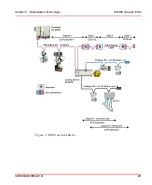
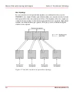
In a ring structure (see
on page 52), the maximum
bridgeable distance between two components is a function of the transmission
rate. A maximum of 15 km can be bridged at a transmission rate of 9.6 kBit/s; at
1.5 MBit/s, only 530 meters
Summary of Contents for AC 800M
Page 2: ......
Page 3: ...AC 800M PROFIBUS DP Installation System Version 5 0 5 1...
Page 8: ...Table of Contents 8 3BDS009029R5001 B...
Page 16: ...Released User Manuals and Release Notes About This User Manual 16 3BDS009029R5001 B...
Page 116: ...Updates in Revision Index B 116 3BDS009029R5001 B...
Page 117: ......


