


Installation hints for electrical data cables
Section 4 Commissioning of PROFIBUS equipment
94
3BDS009029R5001 B
Preparing a PROFIBUS cable (RS485 and MBP)
•
Cut the PROFIBUS cable type A to the required lengths. Strip off the insulation
from the cable ends.
•
Observe the manufacturer instructions for the PROFIBUS connector.
•
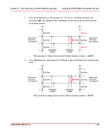
Make sure not to confound feed and return wires. The incoming and outgoing
signals must not be applied to the same pin.
•
Connect the bare (non-insulated) wire ends to the appropriate pins. It is
recommended to note down the wire color to avoid that the data lines will be
confounded when the network will be extended at a later time.
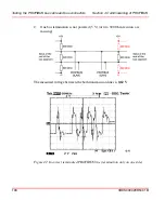
For RS 485 cable, the normal cases wire A / pin 8 has green color and wire B /
pin 3 has red color.
•
Make sure that the braid shield and, if applicable, the tape shield underneath it,
is in good contact with the appropriate connector pin.
•
Switch on the bus termination of the end connectors (no outgoing lines).
•
Connect the cable shield to functional ground e.g. by using a grounding clamp.
•
Put on the shield for every node of a line and make sure there is a good contact.
•
To ensure RFI suppression in accordance with Class B to DIN/VDE install the
ferrite ring RFI suppressor from for example Würth-Elektronik. The
requirements of RFI suppression Class A are always met.
RFI suppression (Class B to DIN/VDE) is only ensured if the PROFIBUS cable is
provided with the ferrite-type RFI suppressor specified above. For installation
hints of RFI suppressor please read the specific manufacturer manual.
Summary of Contents for AC 800M
Page 2: ......
Page 3: ...AC 800M PROFIBUS DP Installation System Version 5 0 5 1...
Page 8: ...Table of Contents 8 3BDS009029R5001 B...
Page 16: ...Released User Manuals and Release Notes About This User Manual 16 3BDS009029R5001 B...
Page 116: ...Updates in Revision Index B 116 3BDS009029R5001 B...
Page 117: ......


