


CEI-100/200 ARINC Test Program
Receive Menu
CEI-100/CEI-200/CEI-
x20 User’s Manual
52
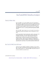
Triggering
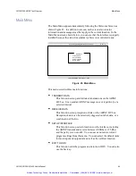
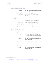
When you select, Setup triggering, the Triggering setup screen appears
(see Figure 31). This screen displays the trigger, broken out bit-by-bit in
logic analyzer format. Each bit position must have an X (don't care), a 1
(must be one), or a 0 (must be zero). If the trigger has an X in all bits, it is
considered inactive and isn’t tested in the triggering logic.
Channel 1 Stopped Triggering off
HEX
Condor Engineering ARINC-429 Controller
Rev 1.0
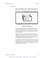
Define message
Repeat / Step
Start transmitting
Return to main menu
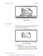
Transmit Menu
Transmission initiated. Enter any key to transmit.
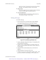
Messages
TRIGGER BITS
32-----------Data-----------9 8-Label--1
XXX XXX XXX XXX XXX XXX XX XXX XXX
Enter 0, 1 or X (don’t care)
Buffer UNTIL trigger
Define Trigger Bits
Figure 31. Trigger Bit Definition
Triggering Logic
As each data word is received, it is checked against the trigger condition.
If the word meets the condition, the trigger status is considered TRUE, and
a trigger has occurred. The trigger condition is met if, for each trigger bit
specified as a 1, the corresponding bit in the data word is a 1, and for each
trigger bit specified as a 0, the corresponding bit in the data word is a 0.
For each bit in the trigger specified as an X, the corresponding bits in the
receive data word are not evaluated.
The buffering mechanism is selected along with the trigger logic. Buffer
UNTIL causes all words, up to and including the one that causes a trigger,
to be buffered. At that point, the buffering is halted. Buffer AFTER
causes all words, including and after the trigger, to be buffered. Toggle
between the two conditions by pressing the space bar.
Artisan Technology Group - Quality Instrumentation ... Guaranteed | (888) 88-SOURCE | www.artisantg.com


