


Installation
Configuring the CEI-220
CEI-100/CEI-200/CEI-
x20 User’s Manual
22
Configuring the CEI-220
This section provides configuration information for the CEI-220.
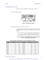
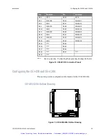
CEI-220 Outline Drawing
Figure 10. CEI-220 Outline Drawing
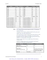
CEI-220 Base Memory Address
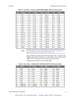
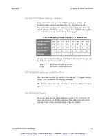
Jumpers A19-A12 set the base memory address for the CEI-220. An
installed jumper selects that address bit as ‘0’. Table 17 demonstrates the
mapping of switch positions to address bits and uses the default address of
D000 (hex) as an example. The CEI-220 takes up 4Kb (i.e., 1000 Hex) of
upper memory block memory space.
Table 17. Mapping of Switch Positions to Address Bits
Jumper Position
A19 A18 A17 A16 A15 A14 A13 A12
Address Bit
19
18
17
16
15
14
13
12
Jumper Setting
Off
Off
On
Off
On
On
On
On
Base address
1
1
0
1
0
0
0
0
Hex value
D
0
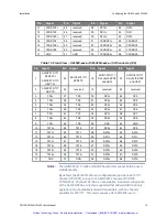
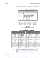
Other sample settings for jumpers A19 through A12 respectively generate
the following base memory addresses:
D800 = Off Off On Off Off On On On
E000
= Off Off Off On On On On On
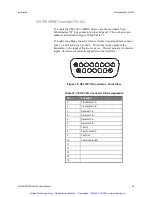
Artisan Technology Group - Quality Instrumentation ... Guaranteed | (888) 88-SOURCE | www.artisantg.com


