


Modifying CEI-200 Base Bit Rate
Procedure
CEI-100/CEI-200/CEI-
x20 User’s Manual
168
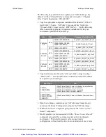
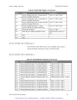
If the “Low” bit rate is programmed, the actual bit rate can be calculated
by dividing the actual “High” bit rate by 8. The “Max” and “Min” values
above represent the maximum calculated range within which the receivers
detect valid data. The transmitters always transmit exactly at the defined
bit rate.
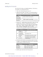
1. From a user application:
After you call AR_LOADSLV, and before calling the routine
AR_GO, you must program a new clock-scaling factor onto the
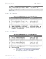
board. The “A” value in Table 48 is a 16-bit value that must be
written to the board at offset 0x490. The “B” value in Table 48 is
a 16-bit value that must be written to the board at offset 0x492.
2. From the AVIATOR or CONDOR programs.
Start the applicable program (AVIATOR or CONDOR).
Create to DOS using the hot key ALT-D. If you don't have
enough memory, free up enough memory by removing TSRs, etc.
From the DOS prompt, run the DEBUG program and manually
modify the values on the board. Offset 0x490 contains a 16-bit
value for the “A” value on the above chart and offset 0x492
contains the “B” value. The following example changes the clock
to 10Kbs for a board configured at the default segment address of
D000:
DEBUG
D D000:490
E D000:490 14 0 14 0
Q
Notice the byte ordering per Intel architecture and hexadecimal notation
for DEBUG input.
Finally, return to the application (type the
Exit
command) and
proceed normally. In this example, the channel parameters as
configured from the SETUP Menu must be set for the HIGH bit
rate (the program says 100K, but it actually is as modified above).
Note:
Artisan Technology Group - Quality Instrumentation ... Guaranteed | (888) 88-SOURCE | www.artisantg.com


