


CEI-100/200 ARINC Test Program
Accessing the Program
CEI-100/CEI-200/CEI-
x20 User’s Manual
43
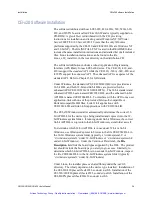
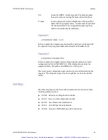
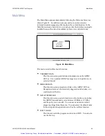
1 CEI-200 ARINC Controller(s) ready
Condor Engineering ARINC-429 Controller
Rev 1.0
ARINC-429 Interface Control Program
Condor Engineering, Inc.
Santa Barbara, California
(805) 965-8000
Copyright (c) 1992 Condor Engineering, Inc.
Enter F1 for help at anytime
Enter any key to start the main program
Figure 22. Welcome Screen
If the message at the bottom of the screen indicates that no interface is
installed, make sure that the proper dipswitch settings have been
selected. If settings other than the default have been selected, make
sure that the program was started with appropriate address switch
arguments.
Accessing the Program
You can use the following command line switches to when calling the
program. They can be used in any order. The default I/O address is 380
(hex). The default segment is CC00 for the CEI-100 and D000 (hex) for
the CEI-200. This program automatically configures for the board type
found at the selected I/O address. All command line switches and
arguments must be separated by at least one space.
/M XXXX
Indicates that the board is installed at a segment address
other than the default. It must be followed with a 4-digit
HEX value for the segment argument.
/I XXX
Indicates that the board is installed at an I/O control
address other than the default. This is a 3-digit HEX
value for the address argument.
/X
Indicates that the board has expanded RAM installed (8K
bytes on the CEI-100 or 32K bytes on the CEI-200) as
opposed to the default.
Note:
Artisan Technology Group - Quality Instrumentation ... Guaranteed | (888) 88-SOURCE | www.artisantg.com


