


Description of CEI-100/200 ARINC Interface
Filtering Out Labels
CEI-100/CEI-200/CEI-
x20 User’s Manual
165
Since it would be redundant to store the label portion of an ARINC word
at the location for that label, the firmware maintains an eight-bit sequence
number in the LSB instead of label number. The sequence number is
incremented each time a word for that label is stored there. The format of
the data is:
byte 0 sequence number
byte 1 ARINC data bits 8
15
byte 2 ARINC data bits 16
23
byte 3 ARINC data bits 24
31
Merged mode is handled in the same way as Buffered mode, except that all
data is merged into the buffer for receive channel 1. It is possible to
increase the buffer size for that channel to include the buffers for the other
receive channels since all receive channels' buffers are contiguous in
memory. You do this by modifying the wrap mask. For example, to
combine the buffers for two consecutive receive channels into one large
buffer, given that each buffer had a wrap mask of 01FFh, the wrap mask
for the combined buffer would be 03FFh. The formula is:
n_channels * (wra 1) - 1
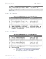
Filtering Out Labels
An on-board filtering mechanism is available which causes the interface to
throw away any undesired labels. This is implemented with a 256-byte
flag array where each byte represents a label, and each bit represents a
channel. Byte 0 contains the filtering flags for label 0, byte 1 contains the
flags for label 1, etc. Bit 0 of a flag corresponds to the first receive
channel. Bit 1 corresponds to the second channel, etc. A set bit causes
that label/channel to be filtered out; a clear bit causes it to be stored. The
flag array starts at location 0300h.
Transmitting Data
Each transmit channel has its own circular buffer which is handled the
same way as in Buffered receive mode. When you desire to transmit data,
you put data in the buffer starting at the offset pointed to by the head
pointer and then update the head pointer to point to the next location. This
is done by adding 4 and performing the bit-wise AND of the wrap mask
and the head pointer and then writing the head pointer back to its dual-port
RAM data structure location. The slave is constantly monitoring the
transmit data structures. Any time it finds the head and tail pointers for a
Artisan Technology Group - Quality Instrumentation ... Guaranteed | (888) 88-SOURCE | www.artisantg.com


