Clearspan® Product Overview R19
Aastra – 2740-007
2014 Clearspan® is a Registered Trademark of Aastra Technologies Ltd.
Page 34 of 93
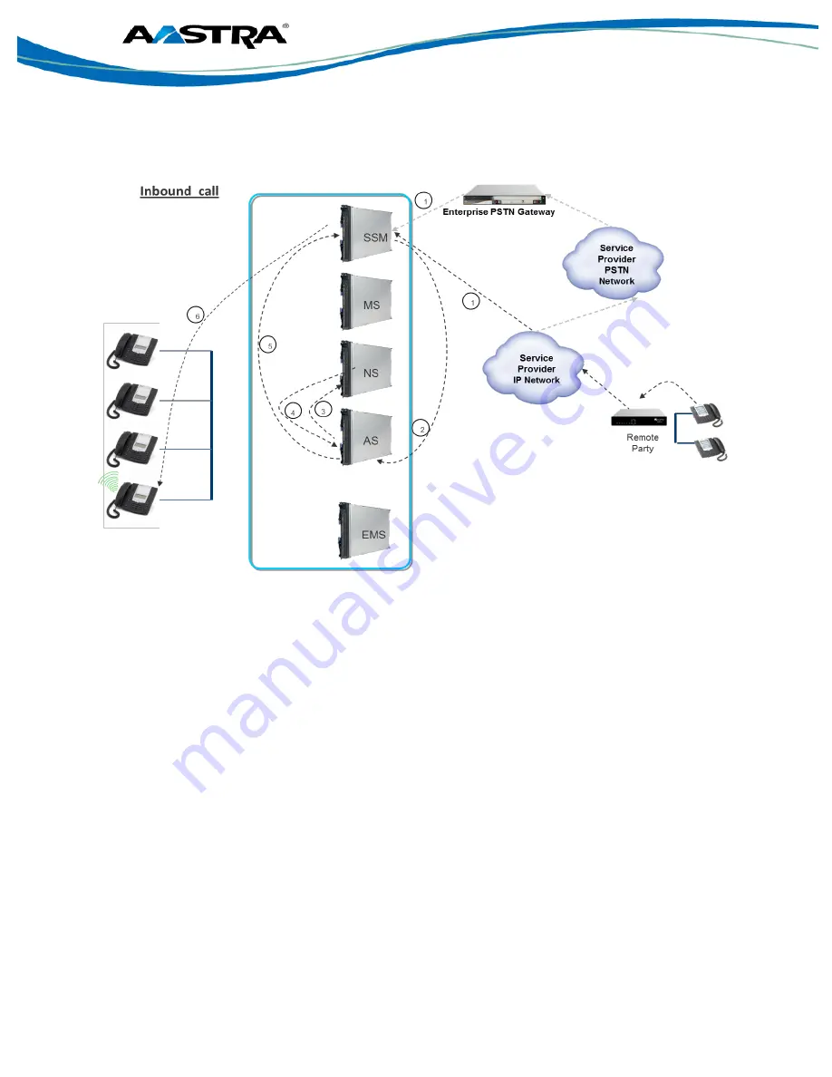
Examining how the inbound call setup is handled within the Clearspan server complex, we see in
the following diagram (Figure 18), that the process involves interworking between the following
servers:
1. For an inbound call, the entry point into the Clearspan node is the SSM, which would
determine whether to provide access (based upon the request being received from a
trusted source) to the signaling request. The request could be received over either the
service providers’ IP network or via the PSTN network if there is a PSTN gateway in place
to handle calls in case of failure of the service providers’ IP network link.
2. The SSM forwards the incoming request to the Application Server (AS) to perform the call
processing function.
3. The AS queries the Network Server (NS) to obtain the required routing and translating
functions required to direct the call setup request to the appropriate SIP endpoint. The AS
also initiates a CDR for record-keeping/accounting purposes.
4. The NS provides the AS with the information on where to route the signaling
– which
internal SIP endpoint the external calling party is attempting to call.
5. Upon receiving the required routing information, the AS forwards the signaling request
back to the SSM to further direct the signaling request to the SIP endpoint.
6. The SSM directs the signaling request to the SIP endpoint to accept the received call.
Upon completing the call setup, the RTP flows directly from the service provider network, through
the SSM, directly to the SIP
user’s terminal, without further intervention from the other Clearspan
servers.
Figure 18. Inbound Call setup Call Flows.


