supply is in the INDEPENDENT operating mode.
B. Adjust "Voltage" control and "Current" control to the desired output voltage and
current.
C. Turn off the power supply and the equipment to be powered during hook-up.
D. Connect the positive polarity of the device being powered to the red (+) terminal of
the power supply.
E. Connect the negative polarity of the device being powered to the black (-) terminal
of the power supply.
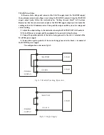
F. Fig.4-2 illustrates the connection procedure.
POWER
SUPPLY
LOAD
M AST ER
SLAVE
+
LOAD
_
+
_
Fig .4-2 Ind ep endent Op eratio n.
Slave tracking error
≤
0.5%+10mV of the master
(No load, with load add Load regulation
≤
300mV).
B. Single supply (Fig.4-3)
2-6 Meter
A. Display: 3 Digits panel meter H3 (0.4 Red LED display H2,0.4 Green LED
display H2)
B. Accuracy:±(0.5% of rdg +2 digits)
(NOTE: Model C/Model D Out OFF Accuracy ±(0.5% of rdg +8 digits)).
C. Voltmeter: 99.9V of full scale.
D. Ammeter: 9.99A of full scale.
2-7 5V Output Specifications
1. Regulation Line regulation
≤
10mV,Load regulation
≤
15mV
2. Ripple & Noise
≤
2mV rms,5Hz~1MHz.
3. Voltage accuracy 5V±0.25V
4. Output current 3A
2-8 Insulation
Between chassis and output terminal 20MW or above (DC 500V)
Summary of Contents for Precision AC- DC Power Supply
Page 12: ...Fig 3 2 Rear Panel...


