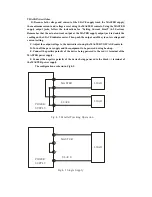
Fig.4-1 Con st an t Volt ag e/Co ns tant Character is tic.
Out pu t Cu rren t
Co ns tant
Ran ge
Vo ltag e
Co ns tant Current
Ran ge
Ou tp ut
Vo ltag e
Cro sso ver
Po in t
VO M AX
IO MAX
(3). Output voltage overshoot
Maybe voltage between output terminals exceeds the present value when the power is
turned on or off.
4-2 Setting Current Limit
(1). Determine the maximum safe current for the device to be powered.
(2). In general, the (+) and (-) terminals of the power supply should be temporarily short
together with a test lead. But in this instrument (Only model C/D), just pushing the output on/off
key can make the short-circuit function.
(3). Rotate the VOLTAGE control away from zero sufficiently for the CC indicator to light.
(4). Adjust the CURRENT control for the desired current limit. Read the current value on the A
meter.
(5). The current limit (overload protection) has now been preset. Do not change the CURRENT
control setting after this step.
(6). Remove the short between (+) and (-) terminals and hook up for constant voltage operation.
4-3 Constant Voltage/Constant Current Characteristic
The working characteristic of this series Power Supplies is called a constant voltage/constant
current automatic crossover type. This permits continuous transition from constant current to
constant voltage modes in response to the load change. The intersection of constant voltage and
constant current modes is called the crossover point. Fig.4-1 shows the relationship between this
crossover point and the load.
For example, if the load is such that the power supply is operating in the constant voltage
Summary of Contents for Precision AC- DC Power Supply
Page 12: ...Fig 3 2 Rear Panel...


