background image

3

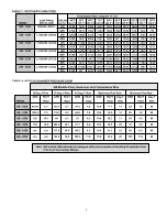
TABLE 4:  HEAT EXCHANGER PRESSURE DROP

GB Models-Flow, Head Loss and Temperature Rise

20 Deg. F Rise

30 Deg. F Rise

40 Deg. F Rise

Maximum Flow Rate

Minimum Flow Rate

GPM

PD-FT

GPM

PD-FT

GPM

PD-FT

GPM

PD-FT

Deg. F

GPM

PD-FT

Deg. F

MODEL

Head

Head

Head

Head

Rise

Head

Rise

GB - 1000

83.16

5.1

55.4

2.7

41.6

1.5

154

12.2

11

42

1.5

40

GB - 1300

109.2

7.2

72.8

4.2

54.6

3.2

154

14.5

14

55

3.2

40

GB - 1500

126

10.1

84

6.3

63

4.3

154

16.3

17

64

4.3

40

GB - 1850

154

18.5

103.6

10.1

77.7

6.4

154

18.5

20

78

6.4

40

GB - 2100

n/a

n/a

117.6

14.5

88.2

8.3

154

21.3

23

89

8.3

40

GB - 2500

n/a

n/a

139.4

18.5

104.6

11.6

154

23.2

28

105

11.6

40

TABLE 3:  RECOVERY CAPACITIES

Temperature Rise - Degrees °F (°C)

Input Rating

Gal/Liter

40°F

50°F

60°F

70°F

80°F

90°F 100°F 110°F 120°F

130°F

MODEL

BTU/Hr. (kW)

per Hr. (22.2°) (27.7°) (33.3°) (38.8°) (44.4°) (50°) (55.5°) (61.1°) (66.7°) (72.2°)

GW - 1000

990,000  (290.1)

LPH

9526

7620

6350

5443

4763

4234 3810

3462

3175

2930

GPH

2520

2016

1680

1440

1260

1120

1008

916

840

775

GW - 1300

1,300,000  (380.9)

LPH

12508 10006

8339

7148

6256

5560 5005

4547

4169

3848

GPH

3309

2647

2206

1891

1655

1471 1324

1203

1103

1018

GW - 1500

1,500,000  (439.5)

LPH

14432 11548

9620

8248

7216

6415 5772

5247

4812

4442

GPH

3818

3055

2545

2182

1909

1697 1527

1388

1273

1175

GW - 1850

1,850,000  (542.0)

LPH

17800 14239 11865 10172

8902

7912 7122

6471

5935

5477

GPH

4709

3767

3139

2691

2355

2093 1884

1712

1570

1449

GW - 2100

2,100,000  (615.3)

LPH

20204 16163 13472 11548 10104 8981 8082

7348

6736

6218

GPH

5345

4276

3564

3055

2673

2376 2138

1944

1782

1645

GW - 2500

2,490,000  (729.6)

LPH

23958 19168 15971 13691 11979 10648 9582

8713

7987

7371

GPH

6338

5071

4225

3622

3169

2817 2535

2305

2113

1950

Note: GW models (GB optional) are equipped with pumps capable of handling 50 equivalent feet

(15.2 m) of normal pipe fittings.

Summary of Contents for 200 Series

Page 1: ...installation and or operation of this boiler Please pay particular attention to the important safety and operating instructions as well as the WARNINGS and CAUTIONS CONTENTS PAGE ROUGH INDIMENSIONS CA...

Page 2: ...Type of Gas Inches W C kPa Volts Hz Amperes GW GB 1000 thru 2500 NATURAL 3 5 0 87 120 60 30 GW GB 1000 thru 2500 PROPANE 10 2 49 120 60 30 All Models Maximum Supply Pressure 14 0 In W C 3 49 kPa Mini...

Page 3: ...2 27 7 33 3 38 8 44 4 50 55 5 61 1 66 7 72 2 GW 1000 990 000 290 1 LPH 9526 7620 6350 5443 4763 4234 3810 3462 3175 2930 GPH 2520 2016 1680 1440 1260 1120 1008 916 840 775 GW 1300 1 300 000 380 9 LPH...

Page 4: ...d by a rate of 4 for each 1 000 feet 300 m above sea level FOREWORD These designs comply with the latest edition of the American National Standards for Gas Fired Low Pressure Steam and Hot Water Boile...

Page 5: ...ignition trials the boiler will lock out Upon lockout manually push the ENTER RESET button on the display panel to restart the boiler WATER FLOW SWITCH The Water Flow Switch is installed at the boiler...

Page 6: ...SUCH THAT IT NATURALLY DRAINS ITSELF If any safety relief valve is replaced the replacement valve must comply with the latest version of the ASME Boiler and Pressure Vessel Code Section IV HEATING BO...

Page 7: ...waxes and process chemicals are typical compounds which are corrosive These materials are corrosive at very low concentration levels with little or no odor to reveal their presence Products of this s...

Page 8: ...1 square inch per 14 000 BTU in excess of 1 000 000 BTUH This opening s shall be located at or ducted to a point neither more than 18 46 0 cm nor less than 6 inches 15 2 cm above the floor level Where...

Page 9: ...he combustion process horizontal terminations must not be located over areas of pedestrian or vehicular traffic i e public walkways or over areas where condensate could create a nuisance or hazard Thi...

Page 10: ...ortion of the vent shall be supported to maintain clearances and to prevent physical damage or separation of joints TABLE 7 STANDARD VERTICAL VENTING CATEGORY I Extending venting over 70 feet 21 3 m m...

Page 11: ...special gas vent pipes listed for use with Category III gas burning heaters such as stainless steel Saf T Vent by Heat Fab Inc available from A O Smith WPC 5621 W 115th Street Alsip IL 60803 Phone 1 8...

Page 12: ...boiler to the vent terminal The horizontal portion of the vent shall be supported to maintain clearances and to prevent physical damage or separation of joints Figure 7 APPLIANCE CERTIFIED EXHAUSTVENT...

Page 13: ...800 433 2515 Pipe joints must be positively sealed TABLE 10 DIRECT VENT HORIZONTAL EXHAUST CONFIGURATIONS Figure 8 APPLIANCE CERTIFIED VENT MAXIMUM AIRINTAKE AIRINLET MAXIMUM MODEL CATEGORY EXHAUSTVEN...

Page 14: ...he Installed vent be airtight Please insure that all joints are sealed properly during installation DIRECTVENTVERTICALANDHORIZONTALVENTING For direct vent applications this boiler may be vented accord...

Page 15: ...minimum pressure drop for several circuits manifolds should be larger than system loops SYSTEM INSTALLATION GENERAL If the system is to be filled with water for testing or other purposes during cold w...

Page 16: ...g that is desired A single boiler installation might be controlled directly from space temperature thermostat s Multiple boiler installations are more effective when the boilers are sequenced in and o...

Page 17: ...ance loop must be installed see figures 11 and 13 HARD WATER CONDITIONS Where hard water conditions exist water softening or the threshold type of water treatment is recommended This will protect the...

Page 18: ...l tank IMPORTANT SAFETY FLOW SWITCH PROTECTS THE BOILER IN CASE OF WATER SERVICE INTERRUPTION OR CIRCULATOR FAILURE PIPE TO OPEN DRAIN X FACTORY INSTALLED ON UNIT SUPPLIED WITH UNIT FIELD INSTALLED IN...

Page 19: ...ED DANGER TEMPERATURE SETTING SHOULD NOT EXCEED SAFE USE TEMPERATUREAT FIXTURES SEE WATER TEMPERATURE CONTROL WARNING ON PAGE 23 IF HIGHER PREHEAT TEM PERATURES ARE NECESSARY TO OBTAIN ADEQUATE BOOSTE...

Page 20: ...92 2 841 2 577 2 372 2 197 2 109 1 962 1 757 1 611 1 464 1 347 Length of Pipe in Feet Metres Nominal Iron Pipe Size Cap 10 Ft 20 Ft 30 Ft 40 Ft 50 Ft 60 Ft 70 Ft 80 Ft 90 Ft 100 Ft 125 Ft 150 Ft 175 F...

Page 21: ...ted Rating Input Number of Model BTUH Burners Natural Holes Propane Holes GB GW 1000 990 000 10 0 111 4X 0 071 3X GB GW 1300 1 300 000 13 0 111 4X 0 071 3X GB GW 1500 1 500 000 15 0 111 4X 0 071 3X GB...

Page 22: ...th a 10 amp fuse located inside the control box Note Four extra 3 amp fuses and one 5 amp fuse are supplied with the boiler Recommended Replacement fuses 3 Amp Littlefuse automotive fuse PN 257003 5 A...

Page 23: ...ssure should read 10 W C IMPORTANT UNDER NO CIRCUMSTANCES SHALL THE GAS PRESSURE MEASUREDATTHE BURNER MANIFOLD EXCEED THAT STATED ON THE BOILER RATING PLATE OVERFIRING WILL RESULT IN DAMAGE TO THE BOI...

Page 24: ...5 MINUTES TO CLEAR OUTANYGAS THEN SMELLFORGAS INCLUDINGNEARTHEFLOOR IFYOU SMELLGAS 1 SET THE SYSTEM CONTROLLER TO THE LOWEST SETTING 2 TURN POWER SWITCH ON APPLIANCE TO OFF POSITION 3 REMOVEACCESS PAN...

Page 25: ...FIEDSERVICE TECHNICIAN TO INSPECT THE APPLIANCE AND TO REPLACEANYPARTOFTHECONTROLSYSTEMANDANY GASCONTROLWHICHHASBEENUNDERWATER E DO NOT OPERATE APPLIANCE UNLESS UNIT IS FILLED WITH WATERAND WATER LINE...

Page 26: ...TER RESET enable the user to adjust set points differentials post circulate time reset the cycle count and reset the control system during lock out Changes made to programmable features are stored in...

Page 27: ...rature Set point Value Set Appliance Stage Switching Differential Value Select Appliance Post Circulate Time Check Appliance Cycle Count View Last Error Encountered by Control Control the water temper...

Page 28: ...n on the display screen when the OUTLET LED is illuminated The red wires control the ECO Emergency Cutoff which shuts down the unit if the water temperature exceeds 250 F 121 C and requires a manual r...

Page 29: ...see the section labeled Procedure for Setting Stage Differential Procedure for Setting Stage Differential Once the system control and set point temperature has been entered the switching differentials...

Page 30: ...set the cycle count to zero press the ADJUST push button Press the ENTER RESET push button to successfully reset the cycle count If the ENTER push button is not pressed the reset function will not be...

Page 31: ...excessive lifting of flame from burner ports see Figure 17 If the preceding burner characteristics are not evident check for accumulation of lint or other foreign material that restricts or blocks the...

Page 32: ...rviceman should follow this procedure when the boiler s intake and exhaust piping need cleaning 1 Turn off the electrical power and manual gas shut off Allow boiler parts to cool before disassembly 2...

Page 33: ...16 red fault LED indicators to help pinpoint the source of failures In addition the display will inform the user on which stage the failure occurred by illuminating a red Stage LED In cases where the...

Page 34: ...RD STAGE 3 013 HARD STAGE 4 014 HARD LWCO 020 HARD CIRCULATE FAULT FLOW SWITCH 030 SOFT INSUFFICIENT AIR AIR PRESSURE SWITCH STAGE 1 041 SOFT STAGE 2 042 SOFT STAGE 3 043 SOFT STAGE 4 044 SOFT BLOCKED...

Page 35: ...ties including any warranty of merchantability imposed on the sale of this boiler under state law are limited to one 1 year duration for the boiler or any of its parts Some states or provinces do not...

Page 36: ...36 REPLACEMENT PARTS 5621 W 115TH STREET ALSIP IL 60803 Phone 800 433 2545 Fax 800 433 2515 www hotwater com E Mail parts hotwater com...

Reviews: