
32
with this boiler should receive periodic (every six months) inspection
to assure proper operation. A low water cutoff device of the float
type should be flushed every six months. Periodic checks, at least
twice a year, should be made for water and/or gas leaks.
More frequent inspections may be necessary depending on water
conditions.
The boiler-mounted gas and electrical controls have been designed
to give both dependable service and long life. However, malfunction
can occur, as with any piece of equipment. It is therefore
recommended that all components be checked periodically by a
qualified serviceman for proper operation.
RELIEF VALVE
The safety relief valve should be opened at least twice a year to
check its working condition. This will aid in assuring proper
pressure relief protection. Lift the lever at the top of the valve several
times until the valve seats properly and operates freely.
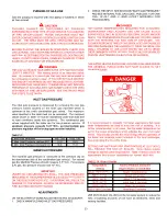
DANGER
THE WATER PASSING OUT OF THE VALVE DURING CHECKING
OPERATION MAY BE EXTREMELY HOT. BEFORE OPERATING
RELIEF VALVE, MAKE SURE DRAIN LINE IS INSTALLED TO DIRECT
DISCHARGE TO A SAFE LOCATION SUCH AS AN OPEN DRAIN,
TO AVOID SCALDING OR WATER DAMAGE.
WARNING
SHOULD OVERHEATING OCCUR OR THE GAS SUPPLY FAIL TO
SHUT OFF, TURN OFF THE MANUAL GAS CONTROL VALVE TO
THE APPLIANCE.
COMBUSTION AIR FILTER
If the combustion air supply to the boiler contains dust, dirt, drywall
dust etc. a filter must be installed. Air filter is not supplied with the
boiler as shipped from the factory. The installer must provide a
filtering system in the air inlet to the boiler if dust, dirt or construction
dirt can be pulled into the boiler through the inlet air piping.
BLOWER COMPARTMENT
The blower compartment should be cleaned annually to remove
any dirt and lint that may have accumulated in the compartment or
on the blower and motor. Buildups of dirt and lint on the blower and
motor can create excessive loads on the motor resulting in higher
that normal operating temperatures and possible shortened service
life.
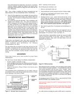
VENTING MAINTENANCE
It is recommended that the intake and exhaust piping of the
appliance be checked every 6 months for dust, condensate leakage,
deterioration and carbon deposits.
WARNING
DO NOT USE A NYLON BRUSH OR OTHER STATIC CREATING
MATERIAL TO CLEAN DUST AND CARBON DEPOSITS FROM
HEATING SURFACES AND VENT. SUCH DEPOSITS ARE
FLAMMABLE AND MAY BE IGNITED BY STATIC ELECTRICITY. USE
A METAL BRUSH TO MINIMIZE THE DANGER OF EXPLOSION.
Qualified serviceman should follow this procedure when the boiler's
intake and exhaust piping need cleaning:
1.
Turn off the electrical power, and manual gas shut-off.
•
Allow boiler parts to cool before disassembly.
2.
Remove the vent pipe.
•
Check parts and chimney for obstructions and clean as
necessary.
3.
Remove burners from boiler and other metal parts as required
to clean as necessary.
•
Refer to parts list supplied with this manual for
disassembly aid.
4.
Clean and reinstall the parts removed in steps 2 and 3.
•
Be sure the vent pipe has a minimum upward pitch of 1/4"
per foot (2 cm/m) of length and is sealed as necessary.
5.
Restore electrical power and gas supply to boiler.
•
Check for gas leaks and proper boiler and vent operation.
HEAT EXCHANGER PREVENTIVE MAINTENANCE
In most water supply systems some solids exist. As the water is
heated, these tend to drop out depositing as scale or lime. This
scale must be removed before the heat exchanger tubes become
blocked.
CAUTION
LIME ACCUMULATION CAN REDUCE THE LIFE OF THE
EQUIPMENT, REDUCE EFFICIENCY AND WASTE FUEL. BOILER
FAILURE DUE TO LIME OR SCALE BUILDUP VOIDS THE
WARRANTY.
DELIMING
The amount of calcium carbonate (lime) released from water is in
direct proportion to water temperature and usage. The higher the
water temperature or water usage, the more lime deposits are
dropped out of the water. This is the lime scale which forms in
pipes, boilers and on cooking utensils.
The usage of water softening equipment greatly reduces the
hardness of water. However, this equipment does not always
remove all of the hardness (lime). For this reason it is recommended
that a regular schedule for deliming be maintained.
The time between cleaning will vary from two to six months
depending upon water conditions and usage. A change of
approximately 5
o
F (3°C) in the normal temperature rise through the
boiler is usually an indication that scale should be removed. For
long life, copper or brass is recommended for all valves, pipe and
fittings.
TUBE CLEANING PROCEDURE
MECHANICAL REMOVAL OF DEPOSITS
Establish a regular inspection schedule, the frequency depends
on the local water conditions and severity of service. Do not let the
tubes clog up solidly. Clean out deposits over 1/16" (1.6 mm)
thickness.
To service heat exchanger tubes remove return header casting,
side opposite the water connections. Use a U.S. standard 5/8"
deep socket ratchet to remove the nuts, exposing the tube ends.
Inspect to ensure tubes are free of scale and deposits. If scaled,
remove deposits with a stiff wire brush or mechanical tube cleaner
to bare metal. Reinstall return header casting. Flush system.
Note: Removal of the heat exchanger is not required.


