


24
Lighting Instructions for the G(B/W) 1000 through 2500 models
A. THIS APPLIANCE DOES NOT HAVE A PILOT. IT IS
EQUIPPED WITH AN IGNITION DEVICE WHICH
AUTOMATICALLY LIGHTS THE BURNER. DO NOT TRY TO
LIGHT THE BURNER BY HAND.
B. BEFORE LIGHTING: SMELL ALL AROUND THE APPLIANCE
AREA FOR GAS. BE SURE TO SMELL NEXT TO THE FLOOR
BECAUSE SOME GAS IS HEAVIER THAN AIR AND WILL
SETTLE ON THE FLOOR.
WHAT TO DO IF YOU SMELL GAS
• DO NOT TRY TO LIGHT ANY APPLIANCE.
• DO NOT TOUCH ANY ELECTRIC SWITCH; DO NOT
USE ANY PHONE IN YOUR BUILDING.
• IMMEDIATELY CALL YOUR GAS SUPPLIER FROM A
NEIGHBOR’S PHONE. FOLLOW THE GAS SUPPLIER’S
INSTRUCTIONS.
• IF YOU CANNOT REACH YOUR GAS SUPPLIER, CALL
THE FIRE DEPARTMENT.
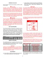
WARNING: IF YOU DO NOT FOLLOW THESE INSTRUCTIONS EXACTLY, A FIRE OR
EXPLOSION MAY RESULT CAUSING PROPERTY DAMAGE, PERSONAL INJURY OR
LOSS OF LIFE.
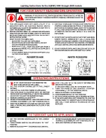
1.
STOP! READ THE SAFETY INFORMATION THE
NEXT STEP ABOVE ON THIS LABEL.
2. SET THE SYSTEM CONTROLLER TO THE LOWEST
SETTING.
3. TURN OFF ALL ELECTRIC POWER TO APPLIANCE.
4. THIS APPLIANCE IS EQUIPPED WITH AN IGNITION
DEVICE WHICH AUTOMATICALLY LIGHTS THE BURNER.
DO NOT TRY TO LIGHT THE BURNER BY HAND.
5. REMOVE CONTROL ACCESS PANEL.
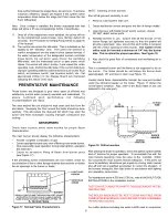
6. REFER TO DIAGRAMS ABOVE. TURN TOP KNOB OF GAS
CONTROL CLOCKWISE
TO “OFF” POSITION, (FIG. A).
7. WAIT FIVE (5) MINUTES TO CLEAR OUT ANY GAS. THEN
SMELL FOR GAS, INCLUDING NEAR THE FLOOR. IF YOU
SMELL GAS,
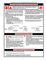
1. SET THE SYSTEM CONTROLLER TO THE LOWEST
SETTING.
2. TURN POWER SWITCH ON APPLIANCE TO “OFF”
POSITION.
3. REMOVE ACCESS PANEL TO EXPOSE GAS CONTROL.
C. USE ONLY YOUR HAND TO PUSH IN OR TURN THE GAS
CONTROL KNOB. NEVER USE TOOLS. IF THE KNOB WILL
NOT PUSH IN OR TURN BY HAND, DON’T TRY TO REPAIR
IT. CALL A QUALIFIED SERVICE TECHNICIAN. FORCE OR
ATTEMPTED REPAIR MAY RESULT IN A FIRE OR
EXPLOSION.
D. DO NOT USE THIS APPLIANCE IF ANY PART HAS BEEN
UNDER WATER. IMMEDIATELY CALL A QUALIFIED
SERVICE TECHNICIAN TO INSPECT THE APPLIANCE AND
TO REPLACE ANY PART OF THE CONTROL SYSTEM AND
ANY GAS CONTROL WHICH HAS BEEN UNDER WATER.
E. DO NOT OPERATE APPLIANCE UNLESS UNIT IS FILLED
WITH WATER AND WATER LINES ARE FULLY OPEN.
STOP ! FOLLOW “B” IN THE SAFETY INFORMATION
ABOVE ON THIS LABEL.
IF YOU DON’T SMELL GAS, GO TO THE NEXT STEP.
8. TURN TOP KNOB OF GAS CONTROL COUNTER-
CLOCKWISE
TO “ON” POSITION, (FIG. B).
9. REPLACE CONTROL ACCESS PANEL.
10. TURN POWER SWITCH TO “ON” POSITION.
11.
SET THE SYSTEM CONTROLLER TO DESIRED SETTING.
12.
IF THE APPLIANCE WILL NOT OPERATE, FOLLOW THE
INSTRUCTIONS “TO TURN OFF GAS TO THE APPLIANCE”
AND CALL YOUR SERVICE TECHNICIAN OR GAS
SUPPLIER.
4.
REFER TO DIAGRAMS ABOVE. TURN TOP KNOB OF GAS
CONTROL CLOCKWISE (TO “OFF” POSITION, (FIG. A).
5.
REPLACE CONTROL ACCESS PANEL.
FOR YOUR SAFETY READ BEFORE OPERATING
OPERATING INSTRUCTIONS
TO TURN OFF GAS TO APPLIANCE


