background image

26

CONTROL SYSTEM

DESCRIPTION OF MULTI-STAGE FIRING SYSTEM

The Central Control Board (CCB) is responsible for staging the
Ignition Control Boards (ICB) and monitoring safety limit devices,
control of circulation pump, power vent, alarm output and IRI gas
valves (only on IRI models).  The thermostat also resides on the
CCB with inputs available for inlet, outlet and tank temperature
probes as well as an input for a remote 24 VAC thermostat.  The
CCB has a display interface which connects to the Display Board
to show system status and failures.  The CCB also has a set of DIP
switches which allows the user to control several system
parameters. (See Figure 14.)

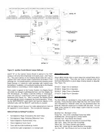
Each stage requires an Ignition Control Board (ICB) which is
responsible for controlling a combustion blower, hot surface igniter
and gas valve.  Each ICB is capable of monitoring gas valve power,
gas valve relay, flame sense and igniter current.  The ICB is
designed to communicate with the Central Control Board (CCB).
Each ICB consists of identical hardware and software.  Each stage
ICB is made unique through the use of circuit board jumpers which
allow the user to control such variables as stage identification and
blower/igniter usage. (See Figure 15 for jumper configurations.)

These jumpers are pre-set at the factory and should only be
adjusted by a qualified service technician.

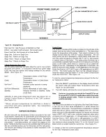
The Display Board allows the end user to monitor water temperature,
set-points, differentials, options, fault indications and error codes.
Display Board pushbuttons labeled "ADJUST", "SELECT" AND
"ENTER/RESET" enable the user to adjust set-points, differentials,
post-circulate time, reset the cycle count and reset the control
system during lock-out.  Changes made to programmable features
are stored in non-volatile memory.

DIA-SCAN II DISPLAY BOARD OPERATING PROCEDURES

The Display Board provides a user-friendly interface to the  Central
Control Board.  With the Display Board, the user can control
appliance functions and view the overall operating status of the
appliance.  If an error condition occurs, the Display Board will indicate
the nature of the fault by illuminating a red LED.  The display will
further define the fault by illuminating a red LED corresponding to
the stage on which the fault has occurred.  Red and green LEDs
are associated with each stage to indicate either a fault or normal
operation.  If the fault continues until the unit "locks out", the display
will show a three digit code in addition to the red LEDs.  (See Table
19 for error code chart.)  Under normal operating conditions, the
four digit LED display on the Display Board will continuously illustrate
the water temperature sensed at the inlet temperature probe.  If dip

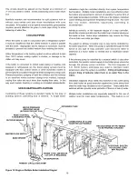
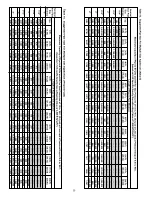
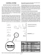
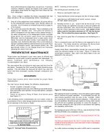
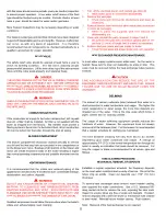
Figure 14. Central Control Board's Dip Switch Configuration and Options

ON

SW1

1  2  3  4  5  6  7  8

A

H

F

E

D

C

B

G

DIP SWITCH CONFIGURATION TABLE

 SW1 OFF

ON

SELECTION:

A

3 STAGE

4 STAGE

EITHER 3 OR 4 STAGE SYSTEM

B

3 TRIALS

1 TRIAL

EITHER 3 OR 1

C

NO IRI

IRI

WHETHER SYSTEM  IS IRI OR

GAS VALVE

GAS VALVE

STANDARD

D

INLET

TANK

INLET OR TANK AS
CONTROLLING PROBE

E

NO EXTERNAL EXTERNAL

WHETHER EXTERNAL

THERMOSTAT THERMOSTAT

THERMOSTAT IS USED

F

OUTLET 210°F OUTLET 240°F OUTLET MAXIMUM TEMPERATURE

G

190°F

220°F

MAX. SET-POINT TEMPERATURE

H

DEGREES °F

DEGREES °C

EITHER °F OR °C FOR DISPLAYED
TEMPERATURE

Summary of Contents for 200 Series

Page 1: ...installation and or operation of this boiler Please pay particular attention to the important safety and operating instructions as well as the WARNINGS and CAUTIONS CONTENTS PAGE ROUGH INDIMENSIONS CA...

Page 2: ...Type of Gas Inches W C kPa Volts Hz Amperes GW GB 1000 thru 2500 NATURAL 3 5 0 87 120 60 30 GW GB 1000 thru 2500 PROPANE 10 2 49 120 60 30 All Models Maximum Supply Pressure 14 0 In W C 3 49 kPa Mini...

Page 3: ...2 27 7 33 3 38 8 44 4 50 55 5 61 1 66 7 72 2 GW 1000 990 000 290 1 LPH 9526 7620 6350 5443 4763 4234 3810 3462 3175 2930 GPH 2520 2016 1680 1440 1260 1120 1008 916 840 775 GW 1300 1 300 000 380 9 LPH...

Page 4: ...d by a rate of 4 for each 1 000 feet 300 m above sea level FOREWORD These designs comply with the latest edition of the American National Standards for Gas Fired Low Pressure Steam and Hot Water Boile...

Page 5: ...ignition trials the boiler will lock out Upon lockout manually push the ENTER RESET button on the display panel to restart the boiler WATER FLOW SWITCH The Water Flow Switch is installed at the boiler...

Page 6: ...SUCH THAT IT NATURALLY DRAINS ITSELF If any safety relief valve is replaced the replacement valve must comply with the latest version of the ASME Boiler and Pressure Vessel Code Section IV HEATING BO...

Page 7: ...waxes and process chemicals are typical compounds which are corrosive These materials are corrosive at very low concentration levels with little or no odor to reveal their presence Products of this s...

Page 8: ...1 square inch per 14 000 BTU in excess of 1 000 000 BTUH This opening s shall be located at or ducted to a point neither more than 18 46 0 cm nor less than 6 inches 15 2 cm above the floor level Where...

Page 9: ...he combustion process horizontal terminations must not be located over areas of pedestrian or vehicular traffic i e public walkways or over areas where condensate could create a nuisance or hazard Thi...

Page 10: ...ortion of the vent shall be supported to maintain clearances and to prevent physical damage or separation of joints TABLE 7 STANDARD VERTICAL VENTING CATEGORY I Extending venting over 70 feet 21 3 m m...

Page 11: ...special gas vent pipes listed for use with Category III gas burning heaters such as stainless steel Saf T Vent by Heat Fab Inc available from A O Smith WPC 5621 W 115th Street Alsip IL 60803 Phone 1 8...

Page 12: ...boiler to the vent terminal The horizontal portion of the vent shall be supported to maintain clearances and to prevent physical damage or separation of joints Figure 7 APPLIANCE CERTIFIED EXHAUSTVENT...

Page 13: ...800 433 2515 Pipe joints must be positively sealed TABLE 10 DIRECT VENT HORIZONTAL EXHAUST CONFIGURATIONS Figure 8 APPLIANCE CERTIFIED VENT MAXIMUM AIRINTAKE AIRINLET MAXIMUM MODEL CATEGORY EXHAUSTVEN...

Page 14: ...he Installed vent be airtight Please insure that all joints are sealed properly during installation DIRECTVENTVERTICALANDHORIZONTALVENTING For direct vent applications this boiler may be vented accord...

Page 15: ...minimum pressure drop for several circuits manifolds should be larger than system loops SYSTEM INSTALLATION GENERAL If the system is to be filled with water for testing or other purposes during cold w...

Page 16: ...g that is desired A single boiler installation might be controlled directly from space temperature thermostat s Multiple boiler installations are more effective when the boilers are sequenced in and o...

Page 17: ...ance loop must be installed see figures 11 and 13 HARD WATER CONDITIONS Where hard water conditions exist water softening or the threshold type of water treatment is recommended This will protect the...

Page 18: ...l tank IMPORTANT SAFETY FLOW SWITCH PROTECTS THE BOILER IN CASE OF WATER SERVICE INTERRUPTION OR CIRCULATOR FAILURE PIPE TO OPEN DRAIN X FACTORY INSTALLED ON UNIT SUPPLIED WITH UNIT FIELD INSTALLED IN...

Page 19: ...ED DANGER TEMPERATURE SETTING SHOULD NOT EXCEED SAFE USE TEMPERATUREAT FIXTURES SEE WATER TEMPERATURE CONTROL WARNING ON PAGE 23 IF HIGHER PREHEAT TEM PERATURES ARE NECESSARY TO OBTAIN ADEQUATE BOOSTE...

Page 20: ...92 2 841 2 577 2 372 2 197 2 109 1 962 1 757 1 611 1 464 1 347 Length of Pipe in Feet Metres Nominal Iron Pipe Size Cap 10 Ft 20 Ft 30 Ft 40 Ft 50 Ft 60 Ft 70 Ft 80 Ft 90 Ft 100 Ft 125 Ft 150 Ft 175 F...

Page 21: ...ted Rating Input Number of Model BTUH Burners Natural Holes Propane Holes GB GW 1000 990 000 10 0 111 4X 0 071 3X GB GW 1300 1 300 000 13 0 111 4X 0 071 3X GB GW 1500 1 500 000 15 0 111 4X 0 071 3X GB...

Page 22: ...th a 10 amp fuse located inside the control box Note Four extra 3 amp fuses and one 5 amp fuse are supplied with the boiler Recommended Replacement fuses 3 Amp Littlefuse automotive fuse PN 257003 5 A...

Page 23: ...ssure should read 10 W C IMPORTANT UNDER NO CIRCUMSTANCES SHALL THE GAS PRESSURE MEASUREDATTHE BURNER MANIFOLD EXCEED THAT STATED ON THE BOILER RATING PLATE OVERFIRING WILL RESULT IN DAMAGE TO THE BOI...

Page 24: ...5 MINUTES TO CLEAR OUTANYGAS THEN SMELLFORGAS INCLUDINGNEARTHEFLOOR IFYOU SMELLGAS 1 SET THE SYSTEM CONTROLLER TO THE LOWEST SETTING 2 TURN POWER SWITCH ON APPLIANCE TO OFF POSITION 3 REMOVEACCESS PAN...

Page 25: ...FIEDSERVICE TECHNICIAN TO INSPECT THE APPLIANCE AND TO REPLACEANYPARTOFTHECONTROLSYSTEMANDANY GASCONTROLWHICHHASBEENUNDERWATER E DO NOT OPERATE APPLIANCE UNLESS UNIT IS FILLED WITH WATERAND WATER LINE...

Page 26: ...TER RESET enable the user to adjust set points differentials post circulate time reset the cycle count and reset the control system during lock out Changes made to programmable features are stored in...

Page 27: ...rature Set point Value Set Appliance Stage Switching Differential Value Select Appliance Post Circulate Time Check Appliance Cycle Count View Last Error Encountered by Control Control the water temper...

Page 28: ...n on the display screen when the OUTLET LED is illuminated The red wires control the ECO Emergency Cutoff which shuts down the unit if the water temperature exceeds 250 F 121 C and requires a manual r...

Page 29: ...see the section labeled Procedure for Setting Stage Differential Procedure for Setting Stage Differential Once the system control and set point temperature has been entered the switching differentials...

Page 30: ...set the cycle count to zero press the ADJUST push button Press the ENTER RESET push button to successfully reset the cycle count If the ENTER push button is not pressed the reset function will not be...

Page 31: ...excessive lifting of flame from burner ports see Figure 17 If the preceding burner characteristics are not evident check for accumulation of lint or other foreign material that restricts or blocks the...

Page 32: ...rviceman should follow this procedure when the boiler s intake and exhaust piping need cleaning 1 Turn off the electrical power and manual gas shut off Allow boiler parts to cool before disassembly 2...

Page 33: ...16 red fault LED indicators to help pinpoint the source of failures In addition the display will inform the user on which stage the failure occurred by illuminating a red Stage LED In cases where the...

Page 34: ...RD STAGE 3 013 HARD STAGE 4 014 HARD LWCO 020 HARD CIRCULATE FAULT FLOW SWITCH 030 SOFT INSUFFICIENT AIR AIR PRESSURE SWITCH STAGE 1 041 SOFT STAGE 2 042 SOFT STAGE 3 043 SOFT STAGE 4 044 SOFT BLOCKED...

Page 35: ...ties including any warranty of merchantability imposed on the sale of this boiler under state law are limited to one 1 year duration for the boiler or any of its parts Some states or provinces do not...

Page 36: ...36 REPLACEMENT PARTS 5621 W 115TH STREET ALSIP IL 60803 Phone 800 433 2545 Fax 800 433 2515 www hotwater com E Mail parts hotwater com...

Reviews: