background image

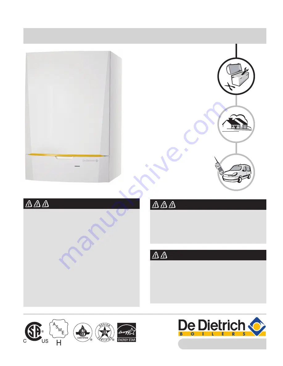
Wall-hung gas-fired condensing boilers

MCA Pro 45/65/90/115

MCA-Pro ISM Rv.4.0  3/2014

www.dedietrichboilers.com

Installation 

and Service 

Manual


DANGER

If you do not follow these instructions exactly, a fire 

or explosion may result causing property damage, 

personal injury or death.

Do not store or use gasoline or other flammable 

vapors and liquids in the vicinity of this or any other 

appliance. 

WHAT TO DO IF YOU SMELL GAS:


• Do not try to light or operate any appliance.

• Evacuate all people.

• Do not try to light any appliance.

• Do not touch any electric switch; do not use any

phone in your building.

• Immediately call your gas supplier from a neighbor's

phone. Follow the gas supplier's instructions.

• If you cannot reach your gas supplier, call the fire

department.

Installation and service must be performed by a 

professional licensed heating contractor, qualified 

installer, service agency or the gas supplier.


WARNING

This manual and all instructions must be read in its 

entirety by a qualified and certified installer with the 

appropriate gas fitter's license for the jurisdiction 

within the area of installation. This manual and ALL 

documentation MUST BE READ BEFORE installation to 

avoid any possible dangerous conditions. Failure to do 

so may create a seriously dangerous situation which 

may cause death, severe personal injury or substantial 

product/property damage.

Product may not be exactly as shown.


DANGER

When using either  PVC, CPVC, Polypropylene or 

stainless steel venting the components must be 

certified according to ULC-S636 and or UL1738. Read 

the Installer and Service Manual prior to installing. 

Failure to follow the instructions in the manuals 

could lead to death, serious personal injury and or 

substantial product and or property damage.

Summary of Contents for MCA Pro 115

Page 1: ...d service must be performed by a professional licensed heating contractor qualified installer service agency or the gas supplier WARNING This manual and all instructions must be read in its entirety by a qualified and certified installer with the appropriate gas fitter s license for the jurisdiction within the area of installation This manual and ALL documentation MUST BE READ BEFORE installation ...

Page 2: ...boiler where it can be accessed for future reference When the installation has been completed the heating contractor has to familiarize the operator owner with the installed equipment as well as any safety precautions and requirements and shut down procedures The heating contractor also needs to inform the operator owner of the need for professional annual servicing of the boiler prior to the heat...

Page 3: ...SM Rv 4 1 2 2017 Safety and Warranty Information 2 Symbols used 2 6 7 10 10 11 12 12 12 12 12 12 13 13 13 13 2 14 14 14 3 15 15 15 16 16 16 16 16 4 18 18 18 18 18 19 19 19 20 21 22 23 25 25 26 27 27 29 30 30 32 32 Table of Contents 9 ...

Page 4: ...0 V control PCB IF 01 60 4 10 3 Connection possibilities for the PCB SCUS02 61 4 11 Electrical diagram 63 4 12 Filling the heating system 64 4 12 1 Water treatment 64 4 12 2 Filling the siphon 64 4 12 3 Filling the heating system 64 5 Commissioning 65 5 1 Control panel 65 5 1 1 Display functions 65 5 1 2 Symbols 65 5 2 Check points before commissioning 66 5 2 1 Preparing the boiler for commissioni...

Page 5: ...nting and air inlet connections 90 7 4 4 Checking combustion 90 7 4 5 Checking the automatic air vent 91 7 4 6 Checking the siphon 91 7 4 7 Checking the burner and cleaning the heat exchanger 92 7 5 Specific maintenance operations 93 7 5 1 Inspection of the ignition electrode 93 7 5 2 Replacing the non return valve 94 7 5 3 Assembling the boiler 95 8 Troubleshooting 96 8 1 Error codes 96 8 2 Shutd...

Page 6: ... cause flue gases to leak into the structure Flue gases leaking into the house can cause injury or death Blocked or partially blocked chimneys must have the blockage removed by a qualified heating contractor Check pressure gauge for correct system water pressure Check for water on the floor from the discharge pipe of the pressure relief valve or any other pipe pipe joint valve or air vent Check fo...

Page 7: ...ed to use a carbon monoxide detector that is in compliance with a nationally recognized standard such as ANSI UL 2034 2002 or CSA 6 19 01 DANGER Improper installation adjustment service or maintenance can cause flue products to flow into living space Flue products contain poisonous carbon monoxide gas which can cause nausea or asphyxiation resulting in severe personal injury or loss of life Codes ...

Page 8: ...ers Chlorinated cleaners and waxes Glues and cements Swimming pool chemicals containing chlorine Refrigerant leaks Water softener salt containing sodium chloride Cleaning products such as chlorine based bleaches detergents and cleaning solvents Spray cans containing chlorofluorocarbons Muriatic and hydrochloric acid Calcium chloride utilized in thawing Permanent wave solutions Adhesives utilized f...

Page 9: ...TING SYSTEM PROVIDED When the manufacturer of Product Approved side wall horizontally vented gas equipment provides a venting system design or venting system components with the equipment the instructions provided by the manufacturer for installation of the equipment and the venting system shall include 1 Detailed instructions for the installation of the venting system design or the venting system...

Page 10: ... operation of the heating system automatically in conjunction with the indoor outdoor control and any programmed settings if applicable Changes to the settings or programming can be made according to separate instructions provided with the boiler control For optimum operation Keep the boiler and the boiler room clean and free of dust and dirt Ensure proper system pressure by occasionally checking ...

Page 11: ...ier s instructions If you cannot reach your gas supplier call the fire department Use only your hand to push in or turn the gas control knob Never use tools If the knob will not push in or turn by hand don t try to repair it call a qualified service technician Force or attempted repair may result in a fire or explosion Do not use this appliance if any part has been under water Immediately call a q...

Page 12: ...tic hot water PCB Printed Circuit Board SU Safety PCB PCU Primary Control Unit PCB for managing burner operation 1 2 General 1 2 1 Operator ultimate owner liability To guarantee optimum and reliable operation of the boiler the Operator ultimate owner must respect the following instructions Read and follow the instructions given in the manuals provided with the appliance Call a professional license...

Page 13: ...or subsequent provisions will apply at the time of installation WARNING Installation of the appliance must be done by a qualified installer in accordance with prevailing local and national regulations 1 3 3 Factory test Before leaving the factory each boiler is set for optimum performance and tested using natural gas and checked for the following items Electrical safety Adjustment CO2 Water tightn...

Page 14: ...pplier call the fire department 2 2 Recommendations WARNING Installation and maintenance of the boiler must be carried out by a qualified professional in compliance with all national and local codes having jurisdiction When working on the boiler always disconnect the power supply and close the main gas inlet valve After maintenance or repair work check all installations to ensure that there are no...

Page 15: ...an be assured by a separate DHW tank Ideal for cascade systems Consult factory The boiler is suitable to operate from sea level to a maximum altitudes of 1370m 4550ft Above 700 2300ft altitude start and minimum fans speed setting should be change 3 2 Main parts 1 Flue gas exhaust 2 Combustion air 3 Boiler casing 4 Heat exchanger 5 Flue gas test port 6 Ignition ionization electrode 7 Manifold pipe ...

Page 16: ...nection An indirect DHW tank can be connected to an individual boiler The DHW tank can be connected to the boiler in two ways Using a three way diverting valve Using a DHW tank pump 3 3 4 Water flow rate The minimum and maximum waterflow as listed on the next page should be taken into account to protect the boiler for to low or high waterflow temperature differences in the heat exchanger The boile...

Page 17: ...ture F C 32 104 0 40 Gas Vent Category Types IV BH ANSI Z21 13a CSA 4 9 Vent Size Single Pipe Inch mm 3 76 2 4 101 6 4 101 64 4 101 6 Vent Size Connection Pipe Inch mm 80 125 100 150 100 150 100 150 Residual Fan Duty inch w c 0 6 0 6 0 7 0 9 mbar 1 5 1 5 1 8 2 2 Water Max Water Temperature Safety Limit F C 230 110 Operating Water Temp Range PVC F C 68 158 20 70 Operating Water Temp Rang CPVC PP SS...

Page 18: ...ssories for wall mounting Wall mount template Connection kit accessory with separate assembly instructions Installation and Service Manual User Guide 3 tubes of X100 water treatment Outdoor sensor These installation and maintenance instructions deal only with the items included in a standard delivery For installation and assembly of any accessories supplied with the boiler see the relevant install...

Page 19: ... in mind the authorised position of the combustion gas discharge outlets and the air intake opening To ensure adequate accessibility to the appliance and facilitate maintenance leave enough service space around the boiler 12 300 mm on the right hand side of the boiler is needed for reading warning and instruction stickers WARNING Mount the appliance to a solid wall capable of bearing the weight of...

Page 20: ...l questions or need assistance with this product please call your local Sales Representative or DDR Americas Inc 1 Distance between the front of the boiler and the internal wall of the cupboard DANGER If the boiler is installed in a closed cupboard respect the minimum dimensions given in the diagram opposite Also allow openings to obviate the following hazards Accumulation of gas Heating of the cu...

Page 21: ... circuit supply pipe 1 Male thread NPT 4 Installation MCA Pro inch mm A Height 29 750 B Width 19 500 C Depth 19 500 D Right side vent 7 191 E Back vent 4 100 F Right side gas pipe 2 50 G Right side supply pipe 5 130 H Right side return pipe 14 365 J P trap 7 191 K Back center of pipe 2 50 L Pipe length of G and H 17 16 36 M Pipe length of F and J 1 40 N Distance between boilers 12 300 4 3 4 a Dime...

Page 22: ...supply pipe 1 Male thread NPT MCA Pro inch mm A Height 29 750 B Width 19 500 C Depth 19 500 D Right side vent 7 191 E Back vent 4 100 K Back center of pipe 2 50 N Pipe length of G and H 5 135 O Pipe length of F and J 2 60 P Supply pipe length 11 282 Q Right side gas pipe 2 50 R Right side supply pipe 5 130 S P trap 7 191 T Right side return pipe 14 365 U P trap length 13 335 V Distance between boi...

Page 23: ...to the wall with masking tape CAUTION Using a water level check that the mounting template is perfectly horizontal During mounting cover up the vent to protect the boiler and its connections from dust and debris Only remove this protection when the vent is fitted The boiler must be installed such that no water can get into the boiler casing and electrical parts of the boiler 2 Drill two Ø 16 mm ho...

Page 24: ...cket Do not install the MCA Pro on the floor or on carpeting If the MCA Pro is to be installed on the floor an optional floor stand is available DANGER When mounting the MCA Pro boiler on a wall make sure the wall is able to support an minimum of 166 6 lbs 75 6 kg and is vertically plumb Failure to heed this warning could result in personal injury property damage or death ...

Page 25: ...is an example reference ONLY Ensure all federal state provincial and local codes are adhered to 1 MCA Pro Boiler 2 Boiler pump with isolation valve 3 Heating load 4 Closely spaced tees 5 Expansion tank 6 Heating system pump with isolation valve 7 Outdoor temperature sensor PRV Pressure relief valve 4 Installation 7 1 3 4 5 PRV ...

Page 26: ...sure all federal state provincial and local codes are adhered to 1 MCA Pro Boiler 2 Boiler pump with isolation valve 3 Heating load 4 Closely spaced tees 5 Expansion tank 6 Heating system pump with isolation valve 7 Outdoor temperature sensor 8 DHW tank pump with isolation valve 9 Check valve 10 DHW tank 11 DHW tank temperature sensor PRV Pressure relief valve ...

Page 27: ...es to be inadequate certain measures must be taken One option for removing pollution is to install a filter Various kinds of filters are available for this A screen filter is designed to trap large dirt particles This filter is usually placed in the full flow part of the system A fabric filter on the other hand is designed to trap finer particles This kind of filter is installed in partial flow co...

Page 28: ...help determine the necessary amount of antifreeze that is required at the specific temperature 3 Using the Technical Specification chart on page 17 determine the water content of the boiler Add the water content volume of the boiler the expansion tank all the components and the complete system piping 4 To figure out he required amount of antifreeze multiply the total water volume calculated in ste...

Page 29: ...asing to distort Step 5 Using a pipe vise attach the female side of the brass union to one end of the 1 NPT x 6 long pipe nipple and attach the 1 X 1 X NPT tee to opposite end of 11 4 NPT nipple Step 6 Install a close nipple onto the 1 x 2 x inch NPT tee to bottom of the assembly Step 7 Install street elbows in inch portion of the assembly ensure the street elbow is facing upwards Step 8 Install s...

Page 30: ...is installed above radiation level a low water cut off device of approved type field supplied must be installed in all instances Do not install an isolation valve between boiler and low water cut off 4 6 3 Connecting the expansion tank Install the expansion tank on the heating return pipe upstream of the boiler pump 4 6 4 Connecting the condensate discharge pipe The boiler comes with a built in co...

Page 31: ...spillage The drain connection must terminate into an open or vented drain as close to the boiler as possible to prevent siphoning of the boiler drain PVC cement and primer must conform to ASTM D2564 or F493 In Canada use CSA or ULC listed schedule 40 CPVC or PVC drain pipe fittings and cement 1 Fit the condensate tube and the siphon to the boiler with water 2 Mount a standard drainage pipe leading...

Page 32: ...er of fittings Type of gas used Maximum input requirements of all gas appliances in the residence Design piping layout in such a way that piping does not interfere with serviceable components 3 Before connecting boiler to gas line install ground joint union capped drip leg and a manual equipment shutoff valve as shown Valves must be listed by a nationally recognized testing agency 4 Make boiler ga...

Page 33: ...tch do not use any phone in your building 4 Installation Immediately call your gas supplier from a neighbor s phone Follow the gas supplier s instructions If you cannot reach your gas supplier call the fire department If you don t smell gas go to the next step 8 Turn ON all electrical power to the appliance 9 Set thermostat s to desired setting 10 The control display will show symbols and text des...

Page 34: ...sistance In Canada Vent types must be an approved type ULC S636 type BH non metallic or metallic vent system In USA ULC S636 and or UL1738 approved vent types non metallic solid PVC CPVC or othe approved non metallic vent system or an approved stainless steel vent system This boiler is factory set for the use of UL1738 or ULC S636 approved PVC venting material To protect the venting system for too...

Page 35: ...isting appliance is connected to the common venting system and the other areas of the building Next turn on the clothes dryer and any other appliances not connected to the common vent system Turn on any bathroom exhausts range hoods and any other exhaust fans to their highest setting so that they are operating at the maximum setting or speed Close the fireplace dampers Do not operate the summer ex...

Page 36: ...serious injury or substantial product property damage WARNING If a masonry chimney is to be used it can only be used as a pipe chase for air and vent pipes The installation instructions in this manual must be followed for the air and vent piping and all joints must be sealed The MCA Pro boiler must be the only appliance using the chimney and no other appliance or fireplace can be connected to the ...

Page 37: ...iler to the termination 6 Install the pipe supports and brackets if required Commonwealth of Massachusetts If the boiler is installed within the Commonwealth of Massachusetts it must Be installed by a professional licensed heating contractor licensed plumber or gas fitter Refer to page 46 or 47 or 48 for sidewall vent air installations WARNING Where the pipe size is different from the termination ...

Page 38: ...vent must terminate A minimum of 6 2 m from any adjacent wall A minimum of 7 2 1 m above any public doorway No closer than 5 1 5 m below a roof overhang A minimum of 3 1 m above any forced air intake within a 10 3 m distance No closer than 12 305 mm below or horizontally from any window door or any other gravity air inlet b The air inlet must have at least a 12 305 mm clearance above the grade or ...

Page 39: ... UL1738 and or ULC S636 ULC S636 AL29 4C Stainless steel piping materials De Dietrich stainless steel bird screens 2 or 3 purchase separately Note 1 De Dietrich concentric vent kits are made from PVC pipe and fittings Manufacturer IPEX Note 2 IPEX PVC concentric terminations utilize PVC pipe fittings certified to ULC S636 Where ULC S636 compliance is required use only IPEX System 636 pipe fittings...

Page 40: ...e to be used to adapt to the appropriate diameter see Vent Travel below Exhaust venting is to be inserted directly into the 4 For PP material use either a 3 transition adapter MCA 35 45 or a 4 transition adaptor fitting Sch 40 to PP MCA Pro 65 90 115 offered by the PP manufacturer M G Dura Vent PolyProTM 4PP AD For PP material exposed to outdoor weather follow the venting supplier s recommendation...

Page 41: ...1738 and or ULC S636 ULC S636 CPVC Schedule 40 80 ULC S636 PP ULC S636 Note IPEX is an approved Manufacturer in Canada supplying vent material listed to ULC S636 Approved plastic intake venting material Material Standards for installation in United States Canada PVC cellular foam Core PVC DWV PVC schedule 40 80 UL1738 and or ULC S636 ULC S636 CPVC schedule 40 80 ULC S636 PP N A N A Note Cellular F...

Page 42: ...eviations PP polypropylene SS AL29 4C stainless steel When using polypropylene or stainless pipe provide adapters for 3 or 4 boiler connections and for terminations when required IPEX 3 PVC concentric vent kits can be used with standard PVC pipe fittings and cement ANSI UL1738 except where ULC S636 compliance is required For ULC S636 compliance all pipe fittings and cement must be IPEX system 636 ...

Page 43: ... and effective manner Do not puncture or drill holes in any portion of the venting the boiler is equipped with a pressure and emission test port Co venting Retrofitting WARNING This boiler must not be co vented with a category I or III appliance Do not co vent the boiler when venting the boiler either direct vent sidewall or in sealed combustion venting application At the time of removal of any ex...

Page 44: ...xterior could be tarnished from the flue gases a shield or another location should be considered Terminals shall not be less than 2 50 mm from the wall surface or more than 10 254 mm from the center line of the terminal to the wall For high traffic locations the vent terminal shall be guarded According to the national gas codes CSA B149 ANSI Z223 1 NFPA 54 a vent shall not terminate Directly above...

Page 45: ...45 MCA Pro 45 65 90 115 MCA Pro ISM Rv 4 1 2 2017 4 Installation H D G C B A E I J F ...

Page 46: ...t meters 1 2 3 4 5 6 7 8 in mm ft m ft m ft m ft m ft m ft m ft m ft m ft m 35 3 80 131 40 118 36 105 32 92 28 79 24 66 20 52 16 39 12 26 8 45 3 80 131 40 118 36 105 32 92 28 79 24 66 20 52 16 39 12 26 8 65 3 80 108 33 95 29 82 25 69 21 56 17 43 13 29 9 16 5 3 1 65 4 100 131 40 115 35 99 30 83 25 67 20 51 16 34 11 18 6 2 1 90 4 100 131 40 115 35 99 30 83 25 67 20 51 16 34 11 183 6 2 1 115 4 100 13...

Page 47: ... 115 35 99 30 83 25 67 20 51 16 34 11 18 6 2 1 90 4 100 118 36 102 31 86 26 70 21 54 16 38 12 21 7 5 2 N A N A 115 4 100 79 24 63 19 47 14 31 9 15 4 N A N A N A N A N A N A N A N A Sidewall vented with sealed combustion air two pipe system MCA Pro Vent ø Max length Number of elbows 45 and equivalent feet meters 1 2 3 4 5 6 7 8 in mm ft m ft m ft m ft m ft m ft m ft m ft m ft m 35 3 80 131 40 127 3...

Page 48: ... 16 5 65 4 6 100 150 98 30 85 26 78 24 72 22 65 20 58 18 52 16 45 14 90 4 6 100 150 98 30 85 26 78 24 72 22 65 20 58 18 52 16 45 14 115 4 6 100 150 98 30 85 26 78 24 72 22 65 20 58 18 52 16 45 14 Vertical vented with sealed combustion air coaxial MCA Pro Vent ø Max length Number of elbows 45 and equivalent feet meters 2 3 4 5 6 7 8 in mm ft m ft m ft m ft m ft m ft m ft m ft m 35 3 5 80 125 98 30 ...

Page 49: ...mbined length MCA Pro Vent ø Max length Number of elbows 90 and equivalent feet meters 2 3 4 5 6 7 8 in mm ft m ft m ft m ft m ft m ft m ft m ft m 35 3 80 131 40 105 32 92 28 79 24 66 20 52 16 39 12 26 8 45 3 80 131 40 105 32 92 28 79 24 66 20 52 16 39 12 26 8 65 3 80 79 24 47 14 31 9 15 4 N A N A N A N A N A N A N A N A 65 4 100 131 40 99 30 83 25 67 20 51 16 34 11 18 6 2 1 90 4 100 131 40 99 30 ...

Page 50: ...80 125 69 21 56 17 49 15 43 13 36 11 29 9 23 7 16 5 65 4 6 100 150 98 30 85 26 78 24 72 22 65 20 58 18 52 16 45 14 90 4 6 100 150 98 30 85 26 78 24 72 22 65 20 58 18 52 16 45 14 115 4 6 100 150 98 30 85 26 78 24 72 22 65 20 58 18 52 16 45 14 Vertical vented with sealed combustion air coaxial MCA Pro Vent ø Max length Number of elbows 45 and equivalent feet meters 2 3 4 5 6 7 8 in mm ft m ft m ft m...

Page 51: ...c The boiler plug must be accessible at all times It is possible to connect various controls safety and regulation systems to the boiler The standard control PCB can be extended with For the optional PCBs see chapter Optional electrical connections page 59 62 4 9 2 Recommendations WARNING Always make sure that the power has been turned off before starting any electrical work Only qualified profess...

Page 52: ... thermostat through the round grommet s on the right in the boiler bottom plate 3 Tilt the control box forwards by opening the holding clips located at the sides 4 Open the control panel cabinet by opening the clip fastener on the front side 5 Run the connection cable s through the grommet s in the control panel cabinet 6 Unscrew the necessary cable clamps to access the connector block and introdu...

Page 53: ...FHP 1 3A it must be connected to the SCU SO2 Accessory See chapter Connection possibilities for the PCB SCU S02 page 59 62 1 Connect the cable that is delivered with the boiler to the pump 2 Remove the grommet from the opening in the middle of the base of the boiler Pass the pump connection cable through the base of the boiler and seal the opening again by tightening the bayonet fitting to the cab...

Page 54: ... 2017 54 3 Connect the pump connection cable to the cable in the instrument box that is connected with connector X8 4 Connect the pump connection cable to the cable bundle by opening and closing the cable bundle bands X8 X81 X81 4 Installation ...

Page 55: ...oller then the boiler supplies this temperature with the set value on the boiler as the maximum Connect ON OFF thermostat Tk ON OFF room thermostat The boiler is suitable for connection to a 2 wire ON OFF room thermostat Install the room thermostat in the reference room generally the living room Connect the 2 wire 24V room thermostat to the ON OFF OT terminals of the connector i If a room thermost...

Page 56: ...g i All wiring must be NEC Class 1 If any of the originally supplied boiler wiring needs to be replaced use only wire with a TEW 105 C or equivalent designation The boiler has to be electrically grounded as required by the latest National Electrical Code ANSI NFPA 70 Heating curve setting F Factory setting Outdoor temperature Supply temperature p1 Supply temperature maximum p25 Supply temperature ...

Page 57: ... thermostat cannot be connected in parallel to the ON OFF OT terminals Implement frost protection for the heating system in combination with an external sensor Frost protection in combination with an outdoor sensor The heating system can also be protected against frost in combination with an outdoor sensor The radiator valve in a room where there is a risk of frost must however be open Connect the...

Page 58: ...ing the Recom PC Laptop service software you can enter change and read out various boiler settings Ws OT On off Tout Tdhw BL RL On off OT BL RL Tout Tdhw OT On off Tou BL RL X13 4 Installation On off OT RL BL Tout Tdhw 4 9 10 Shutdown input The boiler has a shutdown input This input is on the BL terminals of the connector CAUTION Only suitable for potential free contacts i For use of this input re...

Page 59: ...of the input can be changed using p 37 See chapter Parameter descriptions page 76 4 10 Optional electrical connections 4 10 1 Box for the control PCBs The control PCBs are located in the auxilliary control cabinet for PCBs See the instructions provided with the control PCB 1 Unclip the PCB cover 2 Remove the cover i The boiler comes standard with an auxilliary control cabinet for the optional PCBs...

Page 60: ...be connected to the OpenTherm input OT of the boiler control Analogue input 0 10 V This control can be based on temperature or heat output The two controls are described briefly below For analogue control the 0 10 V signal must be connected to the interface Analogue temperature based control The 0 10 V signal controls the boiler supply temperature between 32ºF 0ºC and 212ºF 100ºC This control modu...

Page 61: ...erature control or heat output control Jumper1 Output signal V Temperature ºF ºC Description 0 0 15 Boiler off 0 5 15 20 Alarm 2 0 10 1 20 100 Heat output supplied 1 Dependent on the minimum modulation depth set speeds standard 20 4 10 3 Connection possibilities for the PCB SCU S02 If the boiler is fitted with the control PCB SCU S02 then this is automatically recognised by the automatic control u...

Page 62: ...e pump should be connected as follows N N pump C L pump Ground Control of external gas valve EgV If there is a heat demand an alternating voltage of 120 VAC 1 A maximum becomes available on the EgV terminals of the connector to control an external gas valve Operation signal and failure signal Status The alarm or operation signal is selected using parameter p40 If the boiler is operating the operat...

Page 63: ... Flue gas temperature sensor X1 X14 X13 X12 X3 X2 X4 X5 X6 X7 X8 X9 X10 X11 DIS X14 1 10 1 10 X13 1 PC OT 1 2 X12 3 4 5 6 OS 7 8 WS 9 10 SCU SCU X11 1 2 3 4 5 6 WH GY OR RD GN YW PWM PUMP BK BK 1 2 X116 FTS RTS 10 RD 1 BK 1 2 2 X115 9 BL 1 2 X114 PS 11 BK BK 3 1 X112 4 X10 5 X111 BK BK BK BK 1 2 3 4 PSU 15 13 7 8 6 12 1 2 BK 14 BK 2 4 3 X118 FGTS 3 HLS X9 2 3 4 5 X91 BK BK BK BK 1 2 4 5 FAN 1 BK B...

Page 64: ...iler must be switched on 1 Fill the system with clean tap water advised water pressure is between 22 30 psig 1 5 2 bar 2 Check the tightness of the water connections i After switching on the power and if there is adequate water pressure the boiler always runs through an automatic venting program lasting approximately 3 minutes During filling air can escape from the system via the automatic air ven...

Page 65: ... function is deactivated DHW function Access to potable hot water temperature parameter Manual mode Boiler is set to manual operation Yellow display with the symbols Maintenance message DHW programme deactivated The DHW mode is deactivated Water pressure The water pressure is too low Service menu Parameters at installer level can be changed Battery symbol Status of battery of wireless controller E...

Page 66: ...work i Complete the checklist See chapter Checklist for commissioning page 113 5 2 2 Gas circuit WARNING Ensure that the boiler is switched off 1 Open the main gas supply 2 Open the gas shutoff valve on the boiler 3 Unscrew the two screws located under the front panel by a quarter turn and remove the panel 4 Tilt the control box forwards by opening the holding clips located at the sides 5 Check th...

Page 67: ... fuses Check the fuses on the control panel F1 6 3 AT F2 2 AT Check the connection of the power cable to the connector X1 in the instrument box A fault is indicated on the display by the fault symbol c and a flashing fault code The meaning of the error codes is given in the error table Press for 3 seconds on key Reset button to restart the boiler i If the economy setting eco setting is on then aft...

Page 68: ...etting screw A clockwise until it is closed then Rotate the adjusting screw A on the gas block 3 4 turns in an counterclockwise direction 2 Regulate the Fan Speed as indicated in the table if required The setting can be modified using parameters p17 p18 p19 and p20 See chapter Parameter descriptions page 75 3 Set the air gas ratio For more detailed information See chapter Setting the air gas ratio...

Page 69: ...d with the checking values given in the table Front panel removed 6 If necessary adjust the gas air ratio using the adjusting screw A Control and setting values O2 CO2 at full load natural gas Boiler type Setting value Checking value O2 CO2 O2 CO2 MCA Pro 45 4 7 5 0 8 9 9 1 4 5 5 1 8 8 9 2 MCA Pro 65 4 7 5 0 8 9 9 1 4 5 5 1 8 8 9 2 MCA Pro 90 4 7 5 0 8 9 9 1 4 5 5 1 8 8 9 2 MCA Pro 115 4 5 4 8 9 0...

Page 70: ...given in the table Front panel removed 6 If necessary adjust the gas air ratio using the adjusting screw B Control and setting values O2 CO2 at part load for natural gas Boiler type Setting value Checking value O2 CO2 O2 CO2 MCA Pro 45 5 6 5 9 8 4 8 6 5 4 6 1 8 3 8 7 MCA Pro 65 5 6 5 9 8 4 8 6 5 4 6 1 8 3 8 7 MCA Pro 90 5 6 5 9 8 4 8 6 5 4 6 1 8 3 8 7 MCA Pro 115 5 4 5 7 8 5 8 7 5 2 5 9 8 4 8 8 Co...

Page 71: ...ff valve under the boiler In a red flashing display the fault code E 14 must appear No ignition 12 Tick the gas category used on the rating plate 13 Explain the operation of the installation the boiler and the regulator to the users 14 Give all the instruction manuals to the user 5 6 Reading out measured values The automatic control unit continuously measures various boiler parameters These parame...

Page 72: ...er pressure sensor is connected appears on the display 10 Press the button is displayed alternating with the current modulation percentage for example 11 Press the button The readout cycle starts again with 12 Press the buttons 2 times to return to the current operating mode 5 6 2 Readout from the hour counter and precentage of successful starts 1 Press the two buttons simultaneously and then butt...

Page 73: ...eration 30 Temperature control 31 Limited temperature control ΔT safety 32 Output control 33 Temperature protection gradient level 1 Modulate down 34 Temperature protection gradient level 2 Part load 35 Temperature protection gradient level 3 Blockage 36 Modulate up for flame control 37 Temperature stabilisation time 38 Cold start 4 DHW mode running 30 Temperature control 31 Limited temperature co...

Page 74: ...ump post circulation 61 Pump off 62 Control three way valve 63 Start anti hunting 8 Stop 0 Wait for burner start 1 Short cycling protection function 9 Lock out xx Shutdown codexx 17 Bleed 0 Rest 2 Control three way valve 3 Start pump 61 Pump off 61 Control three way valve 5 Commissioning ...

Page 75: ...tat 2 p5 Anticipation resistance 0 No anticipation resistance for the ON OFF thermostat 1 Anticipation resistance for the ON OFF thermostat 0 p6 Display screen 0 Simple 1 Comprehensive 2 Automatic switching to simple after 3 minutes 3 Automatic switching to simple after 3 minutes Key blocking is active 2 p7 Post circulation of the pump 1 to 98 minutes 99 minutes continuous 3 p8 Brightness of displ...

Page 76: ...heating system operation 2 10 x 10 p29 Setting the pump speed Maximum pump speed for heating system operation 2 10 x 10 p30 Frost protection temperature 22 to 32ºF 30 to 0ºC p31 p31 Legionella protection DHW only 0 Off 1 On After commissioning the boiler will operate once a week at 65 C for DHW 3 Management using a programmable thermostat p32 Set point increase for DHW tank 22 to 32ºF 30 to 0 ºC 3...

Page 77: ...gs may be detrimental to the functioning of the appliance 5 Commissioning Parameter Description Adjustment range 45 65 90 115 p42 HRU connected Optional 0 Not connected 1 Connected p43 Mains detection phase 0 Off 1 On p44 Maintenance message Do not modify p45 Service operating hours Do not modify p46 Service burning hours Do not modify p47 ΔT Modulate down 50 to 104ºF 10 to 40ºC p48 DHW stabilizat...

Page 78: ...ssional To prevent unwanted settings some parameter settings can only be changed after the special access code 0012 is entered CAUTION Modification of the factory settings may be detrimental to the functioning of the appliance 1 Press the two buttons simultaneously and then button until the symbol flashes on the menu bar 2 Select the fitter menu using the button c0dE appears on the display 3 Use o...

Page 79: ...o 115 M Maximum fuel input F Factory setting Q Fuel input MBH kW R Fan rotation speed rpm See the graphs for the relationship between heat input and speed for natural gas The speed can be changed using parameter p17 To do this proceed as follows 5 Commissioning 1500 2500 3500 4500 5500 6500 7500 0 68 3 20 R Q 136 5 40 MBH kW 114 33 3 F M 4100 204 8 60 1500 2500 3500 4500 5500 6500 7500 0 68 3 20 R...

Page 80: ... simultaneously and then button until the symbol flashes on the menu bar 2 Select the installers menu using the button c0de appears on the display 3 Use or button to input the installer code 0012 4 Confirm using button p 1 is displayed with 1 flashing 5 Press the button several times p df is displayed with df flashing 6 Press the button df x is displayed with x flashing This is the current value o...

Page 81: ... Setting the manual mode In some cases it may be necessary to switch the boiler to manual operation For example if the controller has not yet been connected the boiler can be switched to automatic or manual operation under the symbol To do this proceed as follows 1 Press the two buttons simultaneously and then button until the symbol E flashes on the menu bar 2 Press the button or The text with th...

Page 82: ...ost e g a garage or storage room a frost thermostat or outdoor sensor can be connected to the boiler See chapter Frost protection CAUTION The frost protection does not function if the boiler is switched off The integrated protection system only protects the boiler not the installation The pump only start up in the event that the heating pump is controlled by the boilers controls When the heating w...

Page 83: ...iring and ignition Check the wiring and connections Perform start up and verify the performance beginning with the filling of the system Inspect the flame Is it stable and consistent Checking ionization current see page 90 Inspect the boiler gas piping and water piping If the flue temperature is more than 54 F C above the return water temperature the heat exchanger will need to be cleaned Inspect ...

Page 84: ...heat exchanger cover plate gasket and a burner gasket MCA Pro 35 and 45 only Refer to the replacement parts section of this manual as these parts must be on hand to perform the first year inspection and replaced if necessary DANGER A failure to replace the above mentioned items could result in death severe personal injury or substantial product property damage 1 The first year inspection must be p...

Page 85: ... needed 3 Inspect the condensate container the condensate line to the drain and flush if necessary to clean it Ensure the condensate trap is filled with water before operational boiler Refer to chapter 4 12 2 4 Reinstall the condensate trap line and tighten the hose clamps Checking the pipes for leaks WARNING All boiler or system leaks must be eliminated The life of the boiler will be reduced with...

Page 86: ...arge enough remove it From the system and check the charge pressure which is usually 12 psig for residential applications If the expansion tank does not hold the pressure it indicated that the membrane has been damaged The tank will need to be replaced Inspection of the ignition electrode Inspection of the ignition electrode 1 Remove the ignition electrode plug from the ignition transformer i The ...

Page 87: ...scharge line material must conform to local plumbing code or ASME requirements No shutoff valve shall be installed between the relief valve and oiler or in the discharge line WARNING If discharge occurs CALL A PLUMBER IMMEDIATELY A licensed contractor must evaluate the system and determine the cause of discharge and correct the cause immediately Discharge may indicate that an unsafe pressure condi...

Page 88: ...er front plate M6 nuts frontplate Ignition ionization electrode including gasket and screws Insulation plate heat exchanger Non return valve with gasket MCA Pro 35 115 S57241 Sealing heat exchanger front plate MCA Pro 35 115 S54731 Insulation plate heat exchanger MCA Pro 35 115 FAILURE TO REINSPECT THIS VALVE AS DIRECTED COULD RESULT IN UNSAFE PRESSURE BUILD UP WHICH CAN RESULT IN SERIOUS INJURY O...

Page 89: ...tart the next service interval To do this proceed as follows 1 Press the two buttons simultaneously and then button until the symbol flashes on the menu bar 2 Press the button hr and the number of hours of boiler operation 3600 for example are displayed alternately 3 Press button several times until SERVICE flashes on the menu bar 4 Press the button c0dE appears on the display 5 Use or button to i...

Page 90: ...nections Check the tightness of the flue gases evacuation and air inlet connections Check the condition of the vent system Carry out a visual check for the presence of any damages and or corrosion 7 Checking and maintenance 7 4 4 Checking combustion The check on combustion is done by measuring the percentage of O2 CO2 in the flue gas discharge flue To do this proceed as follows 1 Unscrew the plug ...

Page 91: ...tic air vent 7 If any leaks are detected replace the air vent 7 4 6 Checking the siphon WARNING Siphon must always be full WARNING Under no circumstance can trisodium phosphate commonly known as TSP be used to clean a system that contains aluminium This cleaning solution has a very high pH level which will remove the natural protective oxide layer off of the aluminium Although the layer of oxide w...

Page 92: ...so vacuum it up 11 Clean the lowermost part of the heat exchanger with the special cleaning knife accessory 12 The burner does not require any maintenance it is self cleaning If necessary clean the cylindrical burner using compressed air Check that there are no cracks and or other tears on the surface of the dismantled burner If this is not the case replace the burner 13 Checking the ignition elec...

Page 93: ...ignition transformer i The ignition cable is fixed to the ignition electrode and therefore may not be removed 2 Unscrew the 2 screws Remove the unit 3 Wipe off all traces of deposits using an abrasive cloth 4 Check the ignition electrode for wear Replace if necessary 5 When reassembling the front cover alway replace the gasket 7 Checking and maintenance Rinse the heat exchanger pins after the clea...

Page 94: ...do this proceed as follows 1 Remove the air inlet flue on the Venturi 2 Loosen the union on the gas block 3 Remove the plugs from the fan 4 Remove the plugs from the gas block 5 Dismantle the fan 6 Completely remove the fan mixing elbow unit 7 Replace the non return valve located between the mixing elbow and the fan 8 To re assemble perform the above actions in reverse order 7 Checking and mainten...

Page 95: ...it from drawing air from inside the boiler room This is very important especially if other appliances are located in the same room as the boiler Inspect the gaskets of the front boiler casing There should be no tears or gaps in the gaskets If the gaskets are not in good condition replace if necessary If the front casing is not sealed or secured properly it could result in severe personal injury or...

Page 96: ... correctly fitted Replace the sensor if necessary é 03 Supply temperature sensor open circuit Bad connection Sensor fault Sensor not or badly connected Check the wiring Check that the sensors are operating correctly Check that the sensor has been correctly fitted Replace the sensor if necessary é 04 é 05 Temperature of heat exchanger too low Exchanger temperature too high Bad connection Sensor fau...

Page 97: ...rs are operating correctly Check that the sensor has been correctly fitted Check the cleanliness of the heat exchanger é 10 é 11 Difference between the supply and return temperatures too great Sensor fault Sensor not or badly connected No circulation Replace the sensor if necessary Vent the air in the heating system Check the circulation direction pump valves Check the water pressure Check that th...

Page 98: ... opened Check the supply pressure Check the ionization ignition electrode Check the grounding Check the wiring on the ionization ignition electrode é 16 False flame signal Ionization current present when there should not be a flame Ignition transformer defective Gas valve defective The burner remains very hot CO2 too high Check the ionization ignition electrode Check the gas valve and replace if n...

Page 99: ...ay i The boiler starts up again automatically when the reason for the blocking has been removed Error code Description Probable causes Checking solution é 36 5x Flame loss No ionization current Purge the gas supply to remove air Check that the gas valve is fully opened Check the supply pressure Check the operation and setting of the gas valve unit Check that the air inlet and flue gas discharge fl...

Page 100: ...parameter p43 to 0 5 10 Shutdown input is open External cause Parameter error Bad connection Suppress the external cause Check the parameters Check the wiring 5 11 Shutdown input active or frost protection active External cause Parameter error Bad connection Suppress the external cause Check the parameters Check the wiring 5 13 Communication error with the SCU PCB Bad connection with BUS SCU PCB n...

Page 101: ... and setting of the gas valve unit Check that the air inlet and flue gas discharge flues are not blocked Check that there is no recirculation of flue 5 25 1 Internal error on the 5U PCb SU PCB Replace the SU PCB 5 29 FG sensor above maximum setpoint Non existing or insufficient circulation sensor error Replace the flue gas sensor 5 30 No TFG sensor connected shorted Boiler stop Fluegas sensor disc...

Page 102: ...temperature ºF ºC t3 DHW tank temperature ºF ºC t4 Outdoor temperature ºF ºC Only with an outdoor temperature sensor t5 Solar boiler temperature ºF ºC t6 Flue gas tempreature ºF ºC 5p Internal set point ºF ºC fl Ionization current μA Nf Fan speed in rpm pr Water pressure psig bar pO Supplied relative heat output 10 Press the button to interrupt the display cycle ér xx is displayed with xx flashing...

Page 103: ...input the installer code 0012 4 Press the button ér xx appears on the display 5 The fault list or shutdown list can be displayed by pressing the or button 6 Confirm using button ér xx is displayed with xx flashing 7 Press the button several times until ér cl is displayed on the screen 8 Press the button cl 0 is displayed with 0 flashing 9 Press button to modify the value to 1 10 Press the button t...

Page 104: ...y after a boiler inspection or maintenance work that a part needs to be replaced use only original spare parts or recommended spare parts and equipment 9 Spare parts 9 2 Spare parts 9 2 1 Casing 1003 1002 1005 1001 1006 1 To order a spare part give the reference number shown on the list i ...

Page 105: ...anger and burner MCA Pro 35 45 2 2026 2030 2014 2016 2049 2025 2017 2006 2010 2001 2013 2014 2015 2004 2009 2029 2008 2003 2005 2045 2047 2042 2028 2037 2046 2038 2040 2031 2032 2027 2033 2017 2012 2011 2055 2054 2041 2039 2022 2024 2023 2002 2007 2044 2021 2022 2021 2020 2019 2022 ...

Page 106: ... and burner MCA Pro 65 9 Spare parts 2 2027 2017 2017 2016 2030 2014 2006 2010 2001 2013 2014 2015 2004 2009 2029 2008 2003 2005 2047 2028 2026 2032 2031 2033 2012 2011 2002 2007 2049 2025 2045 2042 2037 2046 2038 2040 2055 2054 2041 2039 2044 2024 2021 2021 2022 2019 2022 ...

Page 107: ...nd burner MCA Pro 90 115 9 Spare parts 2 2027 2017 2017 2016 2030 2014 2006 2010 2001 2013 2014 2015 2004 2009 2029 2008 2003 2005 2047 2028 2026 2032 2031 2033 2012 2011 2024 2002 2007 2049 2025 2045 2042 2037 2046 2038 2040 2055 2041 2039 2044 2054 2021 2021 2022 2019 2022 ...

Page 108: ...Pro 45 65 90 115 MCA Pro ISM Rv 4 1 2 2017 108 9 2 5 Fan MCA Pro 35 45 65 9 2 6 Fan MCA Pro 90 9 2 7 Fan MCA Pro 115 9 Spare parts 3006 3014 3007 3013 3011 3010 3001 3015 3016 3005 3012 3003 3008 3009 3002 ...

Page 109: ... Pro 45 65 90 115 MCA Pro ISM Rv 4 1 2 2017 9 2 8 Control Panel 4 9 Spare parts 4006 4007 4018 4019 4002 4015 4004 4015 4001 4011 4023 4023 4024 4025 4008 4007 4025 4003 4016 4014 4012 4010 4017 4009 4005 4013 ...

Page 110: ...tion plate heat exchanger 1 2008 S57241 Sealing heat exchanger front plate 1 2009 S54755 M6 nut 20 2010 S100052 Screw M4 10 20 2011 S103206 Ignition Coil 1 2012 S101509 Screw M4x5 5 2013 7602131 HL temperature sensor 1 2014 S101003 NTC temperature sensor 2 2015 S48950 Screw M4 10 50 2016 7602113 Flue gas discharge pipe Ø80 mm 1 2016 7602115 Flue gas discharge pip Ø100 mm 1 2017 S55914 Sealing ring...

Page 111: ...4765 Venturi 35 45 kW 1 3002 S54766 Venturi 65 kW 1 3002 S57488 Venturi 90 kW 1 3002 S101595 Venturi 115 kW 1 3003 S101543 Air intake silencer 35 45 65W 1 3003 S101520 Air intake silencer 90 kW 1 3003 S101578 Air intake silencer 115 kW 1 3004 S101590 Clamp intake silencer 1 3005 7602122 Gas inlet pipe 1 3005 7602123 Gas inlet pipe 1 3005 7602124 Gas inlet pipe 1 3006 S103193 Gas block 35 45kW incl...

Page 112: ... 1 4007 S101003 NTC temperature sensor 2 4008 7602131 HL temperature sensor 1 4009 S103196 PCU pump cable 1 4010 S103200 24 V cable 1 4011 S103204 Cable harness 115V 35 45 65 90kW 1 4011 S103203 Cable harness 115V 115kW 1 4012 S103199 Electric cable 1500 mm 1 4013 S103208 Pump cable 1 4014 S103197 Cable for fan 1 4015 7602127 Control panel 1 4016 S100852 Protective cover 1 4017 S101514 Fastening 2...

Page 113: ...e connections and the gas pipes 9 Purge the gas supply pipe of the boiler 10 Checking the electrical connections 11 Checking the air supply connections and flue gas discharge connections 12 Checking the functioning and operational status of the boiler 13 Checking the air gas ratio 14 Remove the measuring device and close the measurement points 15 Correctly fit the front housing of the boiler 16 At...

Page 114: ...ation current 7 Checking the burner and heat exchanger heating system 8 Inspection of the ionization electrode ignition electrode 9 Assembling the boiler Replace all removed gaskets 10 Filling and refitting the siphon 11 Checking combustion CO2 Full load Part load 12 Number of operating hours 13 Number of successful starts 14 Service message deleted or service indicator reset 15 Maintenance kit A ...

Page 115: ...5 90 115 MCA Pro ISM Rv 4 1 2 2017 10 Checklists 10 3 Lighting instructions FOR YOUR SAFETY READ BEFOFRE OPERATING OPERATING INSTRUCTIONS TO TURN OFF GAS TO APPLIANCE Closed Open clockwise To close gas valve Front View ...

Page 116: ...Supply F Max OD Reset F Max OD Reset F Max OD Reset F Min OD Reset F Min OD Reset F Min OD Reset F Modulate On Diff F Modulate On Diff F Modulate On Diff F Modulate Off Diff F Modulate Off Diff F Modulate Off Diff F Max On Time minutes Max On Time minutes Max On Time ____ Min On Time ____ Min On Time minutes Min On Time minutes Boost Interval minutes Boost Interval minutes Boost Interval minutes P...

Page 117: ......

Page 118: ......

Page 119: ......

Page 120: ...DDR Americas Inc 1090 Fountain Street North Unit 10 Cambridge Ontario N3E 1A3 Canada Tel 519 650 0420 Fax 519 650 1709 Toll Free 800 943 6275 www dedietrichboilers com info dedietrichboilers com ...

Reviews: