background image

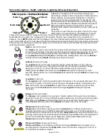
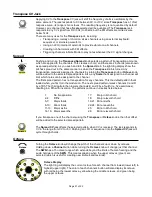
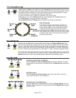
Preset Knob 

The 

Load/Save Preset

 feature is disabled in Sphere Recording Mode. Instead, the 

knob is used for saving a Sphere. 

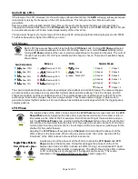
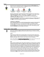
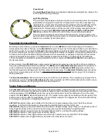
Light Ring Display


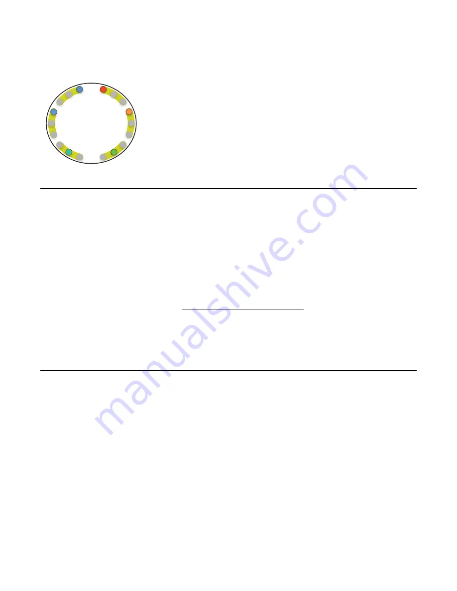
The outer light ring displays a rainbow of lights to help visualize where the recorded 

audio buffer is being split to create the 27 waveforms. The entire outer light ring 

represents the 2.5 seconds of recorded audio, starting at the top right and moving 

clockwise around the circle, ending at the top left. The red end of the rainbow 

represents the first waveform, and the blue end of the rainbow represents the last 

waveform. As you adjust 

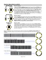
Waveform Spread, Waveform Shift,

 and 

Waveform 

Stretch

 (see below) the lights will move to help you visual these processes. 

The inner light ring displays the position within the Sphere, using the same color 

system that the outer light ring uses when not in Sphere Recording Mode. The first 

waveform is indicated by dim white lights. 

Recording Technical Details

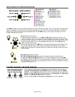
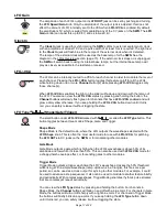
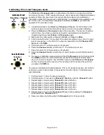
Recording is armed when you press the 

Record 

button, but the 

SWN

 will not start recording until it detects a 

signal greater than about 15mVpp on the 

Waveform In 

jack. The light next to this jack will flash red to indicate it’s 

waiting for a signal. If you press the 

Record 

button again before a signal is detected, recording will be canceled.  

Once recording begins, the light ring will fill up with red lights to indicate its progress. The recording sample rate is 

44.1kHz and enough audio data to fill eight Spheres worth of waveforms is recorded: 8 Spheres (27 waveforms 

each) 512 samples per waveform = 110,592 samples recorded at 44,100Hz = 2.508 seconds. An additional 

130ms of samples is recorded for padding afterwards, which is required for 

Waveform Stretch 

to be applied to 

the last waveform. 

While recording, the 

LFO OUT 

jacks output a series of ramps and pulses (see next section). When recording is 

done, the audio data is split into 27 waveforms. The 

SWN

 sets the 

Waveform Spread 

parameter to maximum in 

order to maximize the space between waveforms (about 93ms). The 

Waveform


Shift 

parameter will be set so 

that the first waveform will begin with the first sample of the recording. The 

Waveform Stretch 

parameter will be 

set so that no re-sampling occurs. See the Waveform Spread, Stretch, and Shift section (page 30) for details on 

these parameters.  

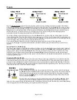
The 

Gain/Normalization 

effect amount will be set to 100% for all waveforms. This normalizes each waveform to 

its maximum volume. The 

Seam Smoothness

 effect amount will be set 100%, which attempts to smooth out any 

discontinuities between the beginning and end of each waveform. 

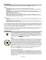
Timing Pulses and Ramps 

The 

LFO OUT

 jacks function as normal in Sphere Recording Mode, except while actively recording. During the 

2.5 seconds of recording, the jacks will temporarily output a series of pulses and ramps to help with synchronizing 

external equipment. The 

LFO Gain

 control can be used to attenuate or boost the maximum value of the ramp 

outputs from 

LFO OUT A, B, 

and

 C

 (default is 5V). The ramps can be useful for modulating a timbal quality of the 

audio source such as a filter or waveshaper, or for scrubbing a sample. The triggers can be useful synchronizing 

an envelope or sequencer, or triggering some event.  

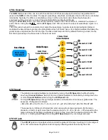
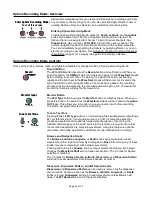
LFO OUT A 

outputs a ramp which starts at 0V and rises to its peak voltage at the end of the 27th recorded 

waveform. It will hold at the maximum value while the padding data is recorded at the end.


LFO OUT B

 outputs a ramp which starts at 0V and rises to its peak voltage every 313ms (27 waveforms worth of 

data). Eight full ramps will be output during recording, plus a partial ramp during the padding data.


LFO OUT C 

outputs a ramp for every 512 samples that’s recorded, including the padding phase.


LFO OUT D

 outputs a 10ms trigger when recording begins.


LFO OUT E

 outputs a 10ms trigger before every block of 27 waveforms is recorded (512*27 samples). 

LFO OUT F 

outputs a 5ms trigger before every block of 512 samples is recorded.

Page   of 

26

32

Summary of Contents for Spherical Wavetable Navigator

Page 1: ...SphereEdit can be freely downloaded and allows you to create edit and convert wav files into Spherical wavetables to transfer into the SWN with an audio cable Six VCOs Voltage Controlled Oscillators each with independent 1V oct pitch CV and waveform selection Twelve spherical wavetables plus space for up 108 user created wavetables Quickly record apply effects and save your own custom wavetables f...

Page 2: ...3 Presets 14 LFOs Overview 15 LFO Speed 15 LFO CV jack 15 Audio Rate LFOs 16 LFO Shapes 16 LFO Phase 16 LFO Gain 17 Clock In 17 LFO VCA 17 LFO Type Shape Gate Trigger 17 Note Mode and Keyboard Mode 18 Resetting and Re syncing LFOs 19 Pitch Overview 20 Transpose Knob 20 Transpose CV Jack 21 Spread 21 Octave 21 Fine Tuning Detuning 22 Spread Detuning 22 Resetting Pitch 22 Scale 23 Channel Jacks 1V o...

Page 3: ... use the right OUT jack Stereo is better if you are able to use it 2 Make sure all six sliders are pushed up to around 75 3 Turn the big center knob slowly and listen to the different sounds timbres This knob is called Browse because it browses the waveshapes in the Sphere We ll talk more about waveshapes and Spheres later 4 Find the Transpose knob in the upper right corner Turn this knob to the l...

Page 4: ...less drawn out with a faster decay 7 If you re feeling confident try adjusting the LFO Speed or Shape of just one channel at at time If you want to learn more about LFO VCA read the section on LFOs page 15 Global vs Local Controlling One Channel at a Time In the last tutorial we held down a Channel button while turning a knob Transpose and Browse to change the pitch and waveshape of one channel at...

Page 5: ...rent Sphere for any or all of the channels This can completely change the sound and lets you explore all of the basic waveshapes the SWN has built in Play with it now Note The main exception to the Gold Push Turn rule is the Preset knob See the Presets Tutorial to learn how to use this knob Fine button You may have noticed the small button at the top center of the module named Fine When you hold d...

Page 6: ...l the light above the LFO OUT jacks are yellow or at least channel C s LFO light is yellow This selects a sine wave for the LFO shape Peek ahead to the color chart of LFO shapes if you want to see all possible shapes 6 Now let s slow down the speed of the LFO so the drone is morphing very slowly Turn the LFO Speed knob down until you see the light above the LFO OUT channel C jack fading very slowl...

Page 7: ...reset Slots that have a preset saved in them will glow a dim yellow 2 Press and release the knob quickly and the slot will flash green 3 Tap the knob again while the green light is still flashing to confirm the load you ll see an animation of green lights while it s loading and the sound will change If you change your mind and don t want to load the preset just do nothing and the light will stop f...

Page 8: ... The SWN smoothly morphs between waveforms as you navigate thus creating new waveforms on the fly A Sphere is so named because you move between the waveforms in three dimensions Latitude Longitude and Depth and each dimension wraps around to the beginning when you reach the end The analogy to a sphere is not perfect see the Mathematical Note page 11 if you re curious about the true geometry of the...

Page 9: ...Sphere You can always find the first waveform because inner ring lights will glow dim gray 5 Now add some effects FX Each of the buttons at the top of the SWN is an FX For example channel A s button is a wavefolding effect See diagram below for all the FX Hold down one of the FX buttons while you turn the Browse knob You should hear the sound change as the FX is added and you should see the light ...

Page 10: ...s Draw and edit waveforms with the Pencil Brush Grab Line and Eraser tools Draw and edit harmonics using the same tools Import existing wav files Load primitives from the Digital Analog FM Glitch categories Apply Effects to waveforms individually or spread across multiple waveforms 3 Save your work by selecting Save Sphere from the File menu Loading a Sphere into the SWN 1 Plug your computer s aud...

Page 11: ...ake a doughnut if you extrude a circle into a cylinder and then bend the cylinder around so the top and bottom faces are touching You can specify any point on the surface of the doughnut with just two numbers an angle of the original circle and a position along the extruded cylinder so the torus surface is two dimensional and clearly exists in a three dimensional space The next step is not as easy...

Page 12: ...the lights in the light ring will change as Latitude changes Applying CV from 0V to 5V will offset the position selected by using the knob Holding down the Fine button while turning Latitude will adjust the Latitude by small amounts Holding down one or more Channel button s while turning Latitude will adjust only those channel s Longitude knob only The Longitude knob control the position within th...

Page 13: ...d selects a different Sphere for each channel Changing the Wavetable Spread selects one of twelve patterns built into the SWN Each pattern defines an offset for each channel which is added to the Sphere selection from the Sphere knob and CV jack Applying CV from 0V to 5V will offset the position selected by using the knob Resetting Navigation and Sphere Selection The navigation position and select...

Page 14: ...s time When you re ready to load just double tap the Load Preset knob and it ll load the preset you previously selected Staging in this way makes it a little easier to do the difficult multi handed transitions which are common in modular performances Copying and Moving Presets Another feature of presets which may not be obvious is that you can copy presets from one location to another Just load th...

Page 15: ...ontrolled by turning the LFO Speed knob without holding down any Channel Buttons Each LFO s clock divider multiplier is controlled by holding down one or more Channel Buttons while turning the LFO Speed knob Turning LFO Speed steps through integer dividers and multipliers of the base or global clock The sequence of integers is as follows 64 48 32 24 16 8 7 6 5 4 3 2 x2 x3 x4 x5 x6 x7 x8 x12 x16 x2...

Page 16: ...s since each shape has multiple zero crossings which fire the trigger gate in complex patterns LFO Phase The relative phase of the LFOs can be set with the LFO Phase feature push and turn the LFO Shape Phase knob Adjusting the phase of a single channel will make it run earlier or later in time relative to the other LFOs For example if two LFOs are firing at the same time and you turn the LFO Shape...

Page 17: ...bled and will glow a dim yellow otherwise If you keep holding the LFO VCA button down until it turns red you can safely release it without toggling the state LFO Type Shape Gate Trigger The small button under LFO VCA marked with is called the LFO Type button This button toggles between three modes Shape Gate and Trigger Shape Mode Shape Mode is the default mode where the LFO outputs the waveshape ...

Page 18: ... you want consistent results with a sequencer that outputs quantized voltages Double quantizing i e once on the sequencer and once with the SWN can lead to unpredictable results If you sequencer or CV source is not quantized then any scale selection on the SWN will work fine Notes can also played by pressing the Channel buttons manually This triggers the envelopes in the same way as changing the C...

Page 19: ...me time The next time this is pressed the LFO phases will be set to 0 60 120 180 240 and 300 for each channel respectively This means the channels will start their waveshape in a sequence Combined with LFO VCA mode this can be used to create a melodic sequence see Tutorial 2 Making a Melody page 4 If the LFOs have very different tempos then the effect of this will not be very distinct Press Preset...

Page 20: ... intentionally built into the wavetable and will not be considered in the following sections on pitch Transpose Knob Turning the Transpose knob shifts the pitch of an oscillator up or down by semitones A common use for this knob is to set intervals between channels creating chords or melodies Holding down one or more Channel button s while turningTranspose will shift the pitch of just those channe...

Page 21: ...ansposition for any channels This the default pattern that s loaded when you first turn the module on The next spread pattern raises channels C and D by a fifth The third pattern then lowers channels E and F by a fourth i e five semitones resulting in a fifth with inversion The patterns continue in a series listed below 1 No transposition 17 Major ninth chord 2 4 Fifths 18 Major eleventh chord 5 7...

Page 22: ...h channel With every click of the knob the outer channels A and F will detune by three cents the middle channels B and E will detune by two cents and the inner channels C and D will detune by one cent Channels A B and C will detune downwards flat and channels D E and F will detune upwards sharp The end result is that each channel s frequency will detune by a different amount A common use for this ...

Page 23: ...ontrol the channel s pitch or level The 1V oct VCA switch selects whether all six jacks control the level VCA or the pitch 1V oct 1V oct When the switch is flipped down the channel jacks control the pitch of each channel The range of the jacks is 0V to 10V which translates to a 10 octave range If the channel has a Scale set then the resulting pitch will be quantized to the selected scale The Trans...

Page 24: ...button will turn red 7 Play and hold a C3 on the sequencer or keyboard 8 Press the Channel A button to latch the C3 All six buttons and LFO lights will turn white 9 To save your calibration values press and hold the Browse knob for three seconds The SWN will return to normal mode and will use these values even after power down If you want to test the new calibration values press Octave and Transpo...

Page 25: ...eform Monitor Button The LFO Type button becomes the Monitor button and flashes green When you press this button the audio from the Waveform In jack will be routed to the Audio OUT jacks This allows you to monitor or cue your audio input before recording The button will glow solid green while monitoring Tune to Test Tone Pressing Fine LFO Type will turn on monitoring while simultaneously outputtin...

Page 26: ... split into 27 waveforms The SWN sets the Waveform Spread parameter to maximum in order to maximize the space between waveforms about 93ms The Waveform Shift parameter will be set so that the first waveform will begin with the first sample of the recording The Waveform Stretch parameter will be set so that no re sampling occurs See the Waveform Spread Stretch and Shift section page 30 for details ...

Page 27: ...samples which results in the pitch changing The colored lights on the light ring signify the amount of Waveform Stretch Holding Fine while pushing Octave and pushing and turning Browse will stretch the waveform by smaller increments Waveform Shift Pushing and turning the Browse knob controls the amount of Waveform Shift which changes the start position of the waveforms The lights on the light ring...

Page 28: ...first sample value This creates a harsh sound when played even if the waveform itself is something simple and pure like a sine wave Seam Smoothing takes the audio data that follows the recorded waveform and cross fades it back into the original waveform creating a seamless loop Since waveforms are almost always repeated in live audio taking some data from the next waveform usually introduces no ex...

Page 29: ...4ms Company website https 4mscompany com SWN SphereEdit is a slight modification of Synthesis Technology s WaveEdit open source software written by Andrew Belt More information about WaveEdit can be found here http synthtech com waveedit Synthesis Technology s website is here http www synthtech com A complete User Manual is available for SphereEdit and should be read if you intend to use the softw...

Page 30: ...ng there was an error Some buttons will turn red to indicate the error code a Stop the file and rewind to the beginning b Check all cables are plugged in tightly c Tap the channel A button and it will go back to flashing green d Play the file again from the beginning 11 If the file loads successfully the SWN will do an animation of blue and green lights on the light ring and the top row of buttons...

Page 31: ...uts Frequency range 0Hz DC 3kHz Minimum Period 24 hours Maximum Amplitude 8Vpp 1V oct inputs channel CV inputs and Transpose CV Voltage range 0V to 10V 10 octave range CV inputs other than 1V oct and Transpose CV Voltage range 0V to 5V Clock input Trigger threshold 1 5V Pulse width must be greater than 1ms User memory non volatile Preset slots 108 Custom Spherical Wavetables 108 Wavetable 512 samp...

Page 32: ...se slot Press 2 sec Tap to confirm Saving a Sphere Save Preset Press Preset LFO Speed Reset LFO Speeds Phase Save Preset Press Preset LFO Shape Reset LFO Shapes Press and hold for one second Full Reset of LFOs Gain Phase Save Preset Phase Tap LFO Phase knob Re phase LFOs Press LFO Speed Shape Toggle Phase Pattern Gain Phase Save Preset Reset Navigation Sphere Press Preset Depth Latitude Sphere Rec...

Reviews: