background image

36 

3M™MicroTouch™ System DST2270DX Integration Guide 

3M Touch Systems, Inc. Proprietary Information – TSD-25739 

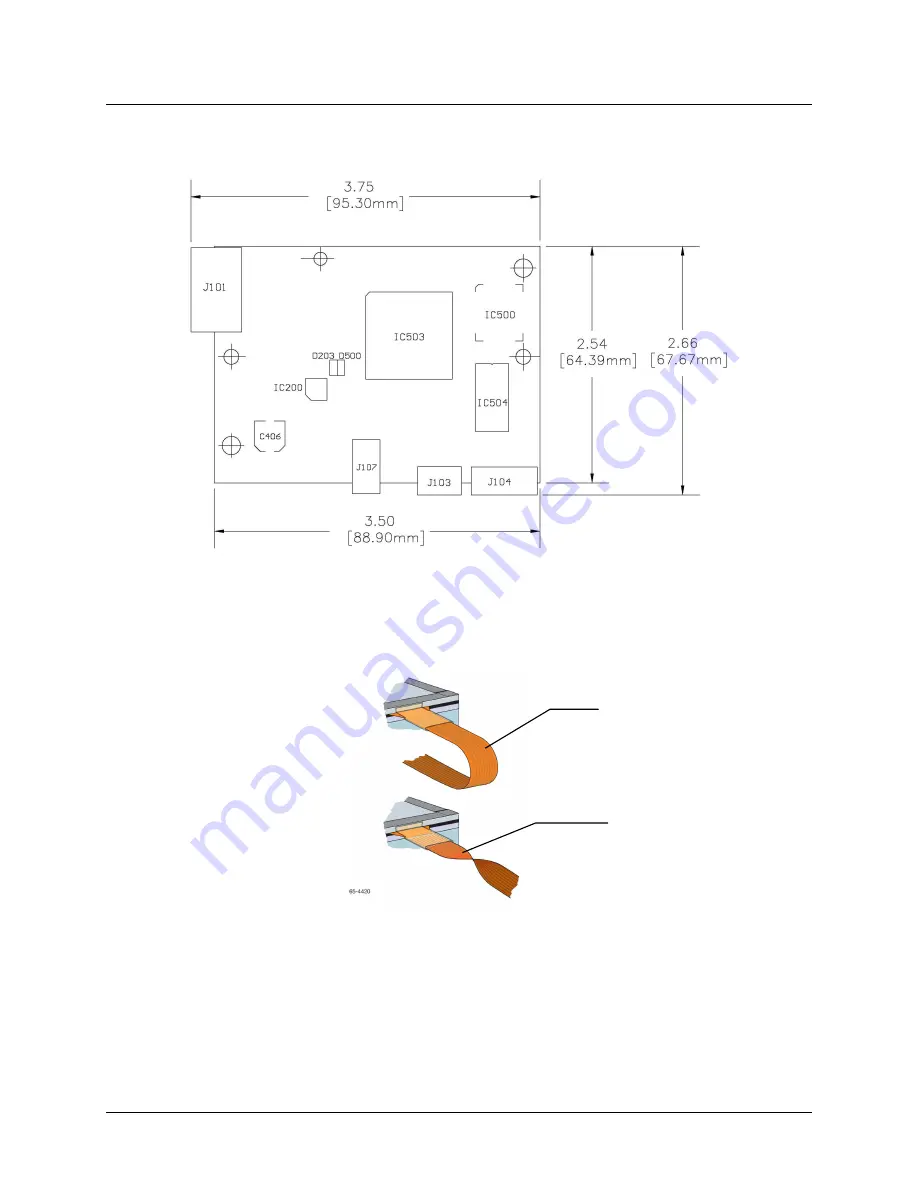
DX123 Controller Overall Dimensions 


Avoid awkward electrical connections by ensuring that the flex tail and controller are 
aligned such that the tail remains straight (90

°

), not pulled or twisted in an odd angle 

from the sensor.  

Recommendation for Flex Tail Connection 


If necessary, to make the sensor flex tail reach to the controller location, you can extend 
the length of the tail with a one-to-one, non-shielded, flat ribbon flex tail extender. The 
connector must be compatible with the connector manufacturer, i.e., Amp should connect 
to Amp. Be sure to use tin compatible contact pins. 

Not Recommended: 
Do Not Twist the Tail  

Recommended: 
Wrap Tail Smoothly  

Summary of Contents for MicroTouch DST2270DX

Page 1: ...3M Touch Systems Inc Proprietary Information TSD 25739 3M MicroTouch System DST2270DX Integration Guide Read and understand all safety information contained in this document before using this product 3 ...

Page 2: ... is not warranted 3M Touch Systems Inc products and software are not specifically designed for use in medical devices as defined by United States federal law 3M Touch Systems Inc products and software should not be used in such applications without 3M Touch Systems Inc express written consent User should contact its sales representative if User s opportunity involves a medical device application I...

Page 3: ...n 11 Preparing Your Work Space 11 Identifying the Components 12 Testing the Display Video 13 Chapter 2 Sensor Design Considerations Before You Begin 15 Mechanical Considerations 15 Grounding Considerations 18 Touch System Location 19 Designing Software Applications 19 Chapter 3 Installing a 3MTM MicroTouch DST2270DX Sensor Handling the Sensor 21 Installation Considerations 23 Disassembling the Dis...

Page 4: ...Controller 35 EMI Considerations 37 Handling and ESD Protection 37 Establishing the Data Connection 37 Supplying Power to the Controller 38 Locating Power for the Controller 39 Completing Controller Mounting 39 Sensor Flex Tail Connector 41 Modifying the Display USB or Serial 42 Turning On Your System 44 Status Light LED Diagnostics 44 Wake on Touch USB Only 44 Installing Software 45 ...

Page 5: ...y make it an ideal choice for large sensor interactive displays 3M Touch Systems is committed to being a premier supplier in touch systems throughout the world As a 3M Touch Systems customer you are aware that we have strong internal programs that meet or exceed environmental regulations of our customers and the regions in which we conduct business What You Need to Know This manual describes how t...

Page 6: ...ble Monday through Friday 8 30 a m to 5 30 p m with limited call back service after 5 30 p m until 8 00 p m US Eastern Standard Time 9 a m to 5 p m throughout Europe You can contact 3M Touch Systems Technical Support US only Eastern Standard Time by calling the hot line sending email or a fax Technical Support Hot Line 978 659 9200 Technical Support Fax 978 659 9400 Toll Free 1 866 407 6666 Option...

Page 7: ...ocedure Be sure to follow all manufacturers recommendations for assembly and disassembly of your flat sensor display Make sure you have the necessary equipment before starting the installation Refer to Supplies and Tools Needed for the Installation later in this chapter Set up a clean comfortable and spacious working area Having sufficient room to work makes the installation easier Test your displ...

Page 8: ... Indicates a potentially hazardous situation which if not avoided will result in death or serious injury and or property damage WARNING Indicates a potentially hazardous situation which if not avoided could result in death or serious injury and or property damage CAUTION Indicates a potentially hazardous situation which if not avoided may result in minor or moderate injury and or property damage N...

Page 9: ...ld result in minor or moderate injury Do not use display if sensor is damaged or broken Team lift the large sensor with at least two people Handle and place the sensor using care and protective gloves To reduce the risk of the potentially hazardous situations associated with the use of isopropyl alcohol which may result in minor or moderate injury or property damage Follow all instructions and rec...

Page 10: ...stain the bezel Apply the cleaner with a soft lint free cloth Avoid using gritty cloths Always handle the sensor with care Do not pull on or stress flex tail Important Notes for Video Displays Plug power cord into appropriate power source Plug power cord into a grounded receptacle When unplugging power supply cord pull on the plug not the cord Do not connect or disconnect this product during an el...

Page 11: ... gasket 3M 4508 Display mounting tape 3M 5962 5925 already installed 5 mil thick polyimide tape Copper tape Tools Needed Flat blade screwdriver with insulated handle Plastic burnisher Razor knife or single edge razor blade Soldering iron Phillips head screwdriver Center punch Power drill Variety of drill tap and spade bits Wire stripper Crimping tool Compressed air optional Dremel tool or nibbler ...

Page 12: ...ng the sensor The pad makes the sensor easier to rotate for fastening screws taping etc Identifying the Components The following components are needed for a successful integration A 3M MicroTouch DST2270DX sensor and mated controller A serial 7319630 or USB cable 7319420 Molex 3 pin power connector crimp housing 22 01 3037 and three terminals 08 50 0114 Software and documentation found on the 3M T...

Page 13: ...d working condition and the video output is functioning properly Your initial test should verify that the video functions properly before you install the sensor You can also compare your results with the results you get after you complete the installation If the display is functioning properly turn off your system disconnect power plugs and disconnect all cables from the display You are ready to d...

Page 14: ...display may have some unique integration considerations the basic installation process consists of the following steps Test that the display s video works properly Disassemble the display if necessary Mount the sensor to the front of the display Install the controller internally Reassemble the display Connect the display and sensor to your computer system Controller LCD Chassis Panel Back Cover Mo...

Page 15: ...adhesive tape Avoid angular creases 45 to the flex tail directly in the area of the tail bond and tape strain relief If it is necessary to remove the sensor from the display after it has been attached do not pry it off Carefully follow the instructions given CAUTION To reduce the risk of glass breakage which may result in minor or moderate injury Do not try to pry the sensor off the LCD if you nee...

Page 16: ...so it does not move Sealing Gasket to Bezel Proper gasketing is critical to any successful sensor integration All displays regardless of environment will be exposed to dust dirt spills and grime and should be sealed with gaskets Gasketing is relatively simple and straightforward 3M Touch Systems strongly recommends that you use single sided 3M vinyl foam tape 4508 for the full perimeter bezel seal...

Page 17: ...ep from interfering with the electrical components on the corners Note For ease of maintenance put a border of polyimide tape around the perimeter of the LCD Then adhere the 3M VHB mounting tape to the polyimide tape The polyimide tape will enable you to easily remove the VHB tape if the need arises Strips of thin foam tape VHB 5962 and VHB 5925 with adhesive on both sides are already attached to ...

Page 18: ...AUTION To reduce the risk of potentially hazardous situations associated with the handling of large sheets of glass which may result in minor or moderate injury or property damage Be sure to exercise extreme caution in handling the edges of the sensor with the copper tape applied The edge of the tape is very sharp For additional EMI shielding 3M Touch Systems has applied a conductive adhesive copp...

Page 19: ...or better readability in bright ambient light conditions Remember that sunlight comes in at different angles throughout the year What might not be a problem in the summer could be an issue in winter The display is a sensitive electronic device Do not install the display in areas where extreme vibrations may be generated For example nearby manufacturing equipment may produce strong vibrations The v...

Page 20: ...the button graphic is 1 inch x 1 inch the active touch area behind it could be 2 inches x 2 inches Be careful to allow sufficient space between buttons also Keep buttons away from the edges and corners of the sensor If this is impossible make sure the active touch areas extend to the outer edges of the viewing area Place buttons horizontally whenever possible One size does not fit all Consider the...

Page 21: ...ce of any product some of which are uniquely within the user s knowledge and control it is essential that the user evaluate the 3M product to determine whether it is suitable for a particular purpose and suitable for the user s intended application Handling the Sensor CAUTION To reduce the risk of lacerations from glass breakage which could result in minor or moderate injury Do not use display if ...

Page 22: ...ople handle the sensor Wear vinyl or nitrile gloves to help eliminate fingerprints and keep the glass cleaner Pick up the glass by the sides rather than the corners to avoid flexing within the glass or damage to the electrical components Make sure to wear an ESD strap to prevent electrostatic discharge to electrical components on the sensor Use ESD foam blocks to support the sensor when laying it ...

Page 23: ...y frame and bezel by the recommended foams The bezel may need to be modified to accommodate the sealing gasket and sensor When trimming the bezel make sure that the mechanical integrity of the display is not compromised If it is necessary to remove the sensor from the display after it has been attached do not pry it off Carefully follow the instructions given in Removing the Sensor Be sure to foll...

Page 24: ...re installation Do not service the display Do not use non conforming replacement parts Do not expose the display to rain or other sources of water steam or moisture To reduce the risk of fire and or explosion which could result in serious injury or property damage Do not use this product in any outdoor environment unless NEMA standards or similar standards such as IP rating are followed CAUTION To...

Page 25: ...stand to the display Be sure to label these for re assembly 4 Remove the stand and set aside Removing the Display Housing 1 Place the display face down on a clean anti static pad Remove the screws that secure the rear housing to the display being sure to label them and set them aside Note The way in which the rear housing is attached to the display varies from model to model Display manufacturers ...

Page 26: ...w need to determine if the sealing gasket and sensor fit into the bezel Note When trimming the bezel make sure you do not compromise the mechanical integrity of the display 1 Place the bezel face down on an anti static pad Be sure the top of the bezel is positioned closest to you 2 Place the sensor face down against the inside of the bezel opening Be sure to orient the sensor so the flex tail exit...

Page 27: ...nsor and associated electronics make sure you wear an ESD strap to prevent electrostatic discharge to electrical components on the sensor Strips of thin foam tape VHB 5962 and VHB 5925 with adhesive on both sides are already attached to the sensor Use these strips to attach the sensor to the display metal frame The sensor must be mounted such that the spacing between the sensor and the display doe...

Page 28: ...signed to be flexible and it may be creased once in a single direction in multiple locations along the flex tail Do not pull tightly on the tail 4 Place the sensor onto the display and ensure that the sensor is straight and the viewing area centered on the LCD Sensor Cleaning Ensure the sensor is clean of debris and fingerprints on both sides before completing the mounting process CAUTION To reduc...

Page 29: ...ase liner from the end of each strip and fold at a 90 degree angle 4 You are now ready to attach the sensor to the display It is recommended that at least two people complete this step Hold the sensor so the flex tail exits from the top turn the sensor over and place it on the display 5 Holding the sensor firmly in place slowly pull out the remainder of the release liner Repeat this with all four ...

Page 30: ...ook at the front of the display and ensure the sensor flex tail exits from the top 3 Check for proper alignment Make sure the sensor is not off center or crooked If the sensor is not correctly aligned with the LCD panel you must remove and remount the sensor before you can continue with the installation 4 Look for dirt or lint trapped between the display and the sensor as these particles will be v...

Page 31: ...e sure to follow solvent manufacturer s precautions and directions for use when using any solvents Follow manufacturer s directions for suitable chemicals for your display Repeat the procedure for properly attaching the sensor to the display Adding a Sealing Gasket to the Bezel 1 Place the bezel face down on an anti static pad 2 Cut strips of the closed cell compressible foam sealing gasket tape 3...

Page 32: ...ace to reassemble the display once the gasket tape and sensor are fully integrated Following is an example of adding spacers to the bezel to accommodate the extra space created by the sensor 1 Insert a temporary post such as a cable tie wrap or toothpick in each bezel hole 2 Place a nylon spacer over each temporary post The size of this spacer will compensate for the thickness added by the sealing...

Page 33: ...e screws Inspect the Attached Display and Bezel Once you attach the display and the bezel inspect your results as follows Check the front of the assembly for proper alignment and adjust if necessary Check that each bezel screw is seated properly and a little tighter than finger tight The screws should not be so tight that they add stress to the display If the bezel is warped loosen the screws Note...

Page 34: ...front of the LCD For information on completing these procedures refer to Chapters 2 3 After you integrate the sensor return to this chapter for the following information Mounting the controller Supplying power to the controller Connecting the controller to the computer Disassembling the Chassis Note When handling the 3M MicroTouch DST2270DX sensor and associated electronics make sure you wear an E...

Page 35: ...internal mounting only Choose a convenient spot away from high voltage high power cables and electronics Use 4 40 metal screws to mount the controller using the two diagonal mounting holes in the board The controller should be mounted in line with the sensor flex tail exit point to minimize tail flexing The controller should be mounted internally behind or on the side of the display on stand offs ...

Page 36: ...0 not pulled or twisted in an odd angle from the sensor Recommendation for Flex Tail Connection If necessary to make the sensor flex tail reach to the controller location you can extend the length of the tail with a one to one non shielded flat ribbon flex tail extender The connector must be compatible with the connector manufacturer i e Amp should connect to Amp Be sure to use tin compatible cont...

Page 37: ...not to the controller directly that may occur during normal operation of the sensor Refer to Appendix A for more detailed specifications Establishing the Data Connection The DX123 controller can operate in either USB or serial mode no need for different controllers You cannot operate in both modes at the same time If you try to connect both USB and serial cables the controller will default to USB ...

Page 38: ...and 6 DCD and DSR 8 DCD DTR DSR 5 Signal Ground 5 Power supply ground 6 Data Set Ready DSR 1 and 4 DCD and DSR 8 DCD DTR DSR 7 Request to Send RTS 1 Request to Send RTS 8 Clear to Send CTS 4 Clear to Send CTS 9 Not Used Do not ground Sleeve 5V 6 DC power jack 5 VDC Pin Ground 7 Cable shield connected to ground DC power jack ground Supplying Power to the Controller The DX123 controller must be self...

Page 39: ...pplied 120 mA Maximum voltage drop allowed 100 mV 50 mV peak to peak voltage ripple To determine the display s voltage drop at the power source conduct the following test 1 Measure voltage across the power source contacts 2 Connect the sensor to the controller and the controller to the power source 3 Power up the display and allow it to warm up for at least 10 minutes 4 Measure voltage across the ...

Page 40: ...unting hole rings 1 We recommend you mount the controller board to the housing using metal screws in the mounting holes nearest the sensor connection and the mounting hole nearest the controller connection 2 Insert a metal thru hole spacer between the controller board and the metal chassis as shown in the following diagram These spacers will prevent the pins and or traces on board from shorting to...

Page 41: ...n 8 pin single row locking female connector that plugs into the controller The calibration process sorts out left right and up down if the sensor is not used in the standard orientation If necessary to make the sensor flex tail reach to the controller location you can extend the length of the tail with a one to one non shielded flat ribbon flex tail extender The connector must be compatible with t...

Page 42: ...l into the electronic circuits Note When routing the sensor flex tail through the metal shield and rear display cover be careful to avoid the inverter and other high noise sources Modifying the Display USB or Serial 1 Select a location on the rear of the display s cover for the sensor connections Note that a serial or USB bulkhead connector and harness may also be used You need to be able to threa...

Page 43: ...e display cover 3 Remount the cover to the chassis assembly 4 Attach the screws put aside during disassembly or use new longer screws as required Installing the Cable Grommet You will also need a grommet to place around the controller cable The grommet seals the opening between the cable and the display cover Attach the grommet around the controller cable Carefully insert the grommet into the moun...

Page 44: ...r custom system ensure that all cables are connected properly and that the controller is properly mounted Be sure to tighten all cable connector screws To start up your system 1 Turn on your display and computer 2 Adjust the contrast and brightness to suit your personal preference and working environment 3 If necessary adjust the horizontal and vertical position controls on the display to center t...

Page 45: ...s well as relevant technical documentation and legacy drivers can be found on the corporate website at www 3Mtouch com After the software is installed restart your computer to load and activate the touch driver Note After you connect your touch display and install software you must calibrate the sensor When using the DX123 controller in USB mode the controller is HID compliant and can be used with...

Reviews: