www.3daeroventures.com
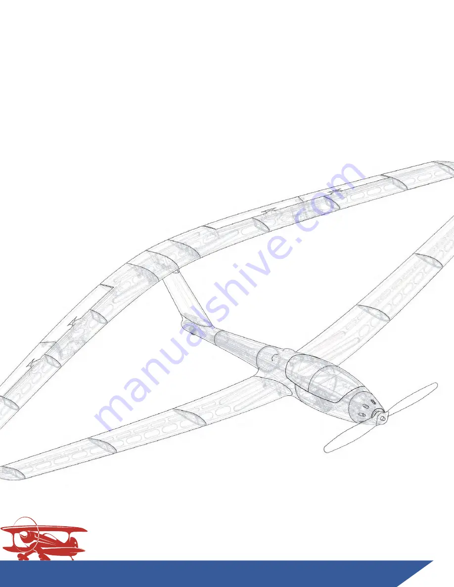
X-100 Infinity Wing V2
3D Printed R/C Aircraft
Build Guide
Wingspan: 1270mm (50”)
3D
Aeroventures
N�v�r S�o� E�p�o�i�g� N�v�r S�o� Q�e�t�o�i�g� N�v�r S�o� P�a�i�g
w�w�3�A�r�v�n�u�e�.�o�
- 1 -
Page 1: ...www 3daeroventures com X 100 Infinity Wing V2 3D Printed R C Aircraft Build Guide Wingspan 1270mm 50 3DAeroventures N v rS o E p o i g N v rS o Q e t o i g N v rS o P a i g w w 3 A r v n u e o 1 ...
Page 2: ...tomeet severalgoals Improvedstallperformance betterprintability surfacequality increasedpartstrength theabilitytoprintthepartsinanymaterial PLA ABS ASA PETG andespeciallyLW PLAorLW ASA and muchsimplerslicingandtheabilitytouseanyslicer likePrusaSlicer Iamnowabigproponentofusing multiplematerialtypestobuildagoodperformingandlong lastingcraft Soyoushouldfindthisstyleofpart designtobesimplertosliceonyo...
Page 3: ... 5 WingLoading PLA 17 6oz ft WingCubeLoading PLA 10 1 FlightPerformanceCategory GeneralSportandScaleAerobatics CenterofGravityLocation 45mminFrontofTrailingEdgeattheWingRoot WeightofPrintedParts LW PLAHybrid 684g 24 1oz WeightofPrintedParts PLA 1048g 37oz FlyingWeight 3S2200mAh 1130g LW PLA to1520g PLA 39 9 53 6oz RecommendedMaxFlyingWeight 1800g 63 5oz No ofChannels 3 Throttle Aileron Elevator El...
Page 4: ... www mcmaster com 90380a011 https www mcmaster com 91290a572 https www mcmaster com 91290a572 RecommendedSetup MotorOptions EFlitePower15 Leopard3536 7T1100kV ormotorwithequivalentXmountingpattern ESCOptions 40Aor50AEsc likeHobbyWingSkywalkerSeries40AESC Rec Prop 12x8 EFlite or11x6 Leopard FoldingPropeller Battery 3S2200mAhLiPoor 4S2200 3300mAh Radio RadiowithElevonMixingCapability 4ChannelRecieve...
Page 5: ... 14 LW PLA 22 Back WingR5 15 LW PLA 23 Back WingL1 13 LW PLA 20 Back WingL2 25 LW PLA 38 Back WingL3 15 LW PLA 26 Back WingL4 14 LW PLA 22 Back WingL5 15 LW PLA 23 Front WingR1 40 LW PLA 60 Front WingR2 31 LW PLA 47 Front WingR3 27 LW PLA 40 Front WingL1 40 LW PLA 60 Front WingL2 31 LW PLA 47 Front WingL3 27 LW PLA 40 Back WingTipR 8 LW PLA 18 Back WingTipL 8 LW PLA 18 Front WingTipR 8 LW PLA 18 F...
Page 6: ... PLAat250ºCelciusandstandard PLAat225ºCelciusbutexperimentwithyourprintertomakesure youachievestronglayeradhesion Ifyouwishtoprintthisaircraft fromadifferentmaterial referencetheincludedSlicerSettingsPDF anduseyourpreferredslicer Option2 Simplify3DFactoryFiles IfyouprefertouseSimplify3Dasyourslicer open theincludedFactoryFilesandeditthepresetprofiles foryourprinter materialtoensureniceoutersurfaces ...
Page 7: ...rsurfaces whenkeepingthefanspeedupto20 withoutnegatively affectinglayerbonding Experimentwithfanspeedsset between0 20 ColorFabbLW PLA ColorFabbLW PLAisaninterestingmaterialthatusesfoaming technologytoachievelightweight lowdensityPLAparts This materialisprintedatahighertemperature whichcausesit toexpand andamuchlowerextrusionmultiplierthanstandard PLA Inordertodeterminethepropernozzletemperatureand...
Page 8: ...rusionmultiplier Elephant sFoot Trytoavoidthefirstfewlayersofeachprintfrom squishingtoofaroutsidethedesignedwalldimensions alsoknownas elephant sfoot Thiscanbecausedby yournozzlebeingtooclosetotheprintbedorfirstlayer widthsettoohighinyourslicer Asmallamountof elephant sfootisokaybuttoomuchwillinterferewith thedesignedalignmentaids SupportStructures Afewpartsofthisaircraftrequiresupport structuresa...
Page 9: ...o i g N v rS o P a i g w w 3 A r v n u e o 9 Alandinggearandrudderupgradepackageisnowavailable fortheX 100InfinityWingV2 Itincludesaseparatefuselage filesetwhichiscompatiblewiththewingsincludedinthisfile set Learnmoreatwww 3daeroventures com shop Step by StepBuildGuide cont d ...
Page 10: ...ont d PrintedPartsNeeded FuseTray1 PLA Fuse1 FuseTray2 PLA FuseTray3 PLA Tailwheel Tire TPE TireHub1 TireHub2 Fuse2 Fuse3 Fuse4 VertStab BackWingR1 BackWing L1 Canopy2 Canopy1 HardwareNeeded linkstorecommendedhardwareonpg4 M3x0 5mmThreadHeat setThreadedInsertsforwingbolts x8 3mmO D CarbonFiberrodorequivelentO D woodorplasticdowelforwheelaxleandcanopy 5mmO Dx3mmThickRareEarthMagnetsforRemovableCano...
Page 11: ...se2 two inpartBackWingR1 andtwoinpartBackWingL1 Step2 1 HeatSetInserts Usingarotarytool Dremel mitersaw orhandsaw cutyour6mmcarbonfiber wingtubestotheproperlengths Youwillneed Qty 3 300mmlong Qty 1 200mmlong Step2 2 Cut6mmO D CarbonFiberTubestoLength www 3daeroventures com 3DAeroventures N v rS o E p o i g N v rS o Q e t o i g N v rS o P a i g w w 3 A r v n u e o 1 Step by StepBuildGuide cont d ...
Page 12: ...arateFuseTrayparts Thiswasdone incaseyouchoosetoprinttheFusepartsinLW PLAorLW ASA TheFuseTrayparts shouldbeprintedinamorerigidplasticlikestandardPLA ABS PETG orPC TheFusepartsmustbeassembledwiththeFuseTraypartsinacertainorder You willnoticetheFuseTraypartsslideintorailslocatedintheFuseparts TheTrays overlapthe seamsoftheFusepartsandmakeforaverystrong rigidfuselage DONOTGLUEALLOFTHEFUSEPARTSTOGETHE...
Page 13: ...1 StartingwithFuse1 applyCAadhesivetotherailswhereFuseTray1slides intoplace EnsureFuseTray1isfullyseatedintoplaceintherail behind thefirewallandwipeoffanyresidualgluefromtheFuse1surfacethat mateswithFuse2beforeapplyingCAAcceleratortosecurethebond 2 3 2 ContinueGluingtheFuseandFuseTrayparts together followngtheorder shownintheimagebelow NOTE PartFuse2containsasacrificialsupport structureinthewheelb...
Page 14: ...tiedtotheother end Usetheweightedstringtoaidinroutingtheextension ALWAYSTESTYOUREXTENSIONSANDSERVOSPRIORTOINSTALLATION 2 3 5 GluetheVertStab BackWingR1 BackWingL1sub assemblytoyour FuselageassemblyusingCAglue Thebuiltinalingmenttabswillkeep allpartswellaligned 2 3 3 GluepartsBackWingR1andBackWingL1togetherusingCAglue Usethe 6mmcarbonfibertubestoensuregoodalignmentbetweenthetwoparts beingcarefulnot...
Page 15: ... v n u e o 1 Step by StepBuildGuide cont d 2 3 6 UseaSolderingIronorahotknifetoremovethesupportpanel inthe canopyareaofpartsFuse1andFuse2 Cleanuptheedgewithsandpaper 2 4 1 TireHub1andTireHub2aredesignedtobeinsertedintoeachopensideof theTire TPEcomponent InsertTireHub1intoonesideoftheTPETire apply asmallamountofCAgluetothematingfaceof thehubandinsertTireHub2 intotheothersideoftheTPETire ...
Page 16: ...isfullyrecessedinthebellywheelaxlehole Insertyourwheelintothewheelbay insertyourwheelaxleandapplyasmall dropofCAglueintobothsidesoftheaxleholetokeepitinplace 2 4 3 Usea3mmcarbonfiberrod woodendowelorplasticdowelasyourtailwheel axle Cuttheaxletolengthsoitisfullyrecessedinthetailwheelaxlehole locatedatthebottomofFuse4 Insertyourtailwheelintothewheelbay insertyourwheelaxleandapplyasmalldropofCAgluein...
Page 17: ...metercarbonrod woodendowel orplasticdowelsinto qty 3 10mmlongpieces Thesesmalldowelpinswillbeusedtoalign partsCanopy1andCanopy2forgluing Step2 5 AssembletheCanopy 2 5 3 Insertyour3mmdiameterpinsintopartCanopy1 applygluetothe matingfaceandmatetopartCanopy2 2 5 1 UseaSolderingIronorahotknifetoremovethesupportpanel onbothCanopy1andCanopy2 Cleanuptheedgewithsandpaper ...
Page 18: ...pinyourmagnet Thematingmagnetscanthenbegluedintothe magnetrecessesinpartFuse2 BEEXTRACAREFULTOGLUETHESE MAGNETSINTHEPROPERORIENTATIONSOASTOATTRACTANDNOT REPELLTHEMATINGMAGNET www 3daeroventures com 3DAeroventures N v rS o E p o i g N v rS o Q e t o i g N v rS o P a i g w w 3 A r v n u e o 1 Step by StepBuildGuide cont d ...
Page 19: ...1 1 GluepartsFrontWingR1 FrontWingR3 togetherusingCAglue Sprayaccelerator onthejointtospeedcuringoftheCAglue Thebuiltinalingmenttabswillkeepall partswellaligned Youcanthenglueon partFrontWingTipR 3 1 2 Repeatthepreviousstepforthefrontleft wing usingpartsFrontWingL1 Front WingL3andFrontWingTipL Step3 1 GlueTheFrontWingPartsTogether FrontWingTipR FrontWingR3 FrontWingR2 FrontWingR1 NOTE PartsFrontWi...
Page 20: ...rdware ElectronicsNeeded linkstorecommendedhardwareonpg4 M3x0 5mmThreadHeat setThreadedInsertsforwingtipbolts x4 Wingservos x2 mountingscrewsincludedwithservos M2or 2x3 8 LongThreadFormingorTappingScrewsformountingservocovers 1mmO D x400mmLongCarbonfiberrodorSteelWireforElevonHinges 3mmO D CarbonFiberrodorequivelentO D woodorplasticdowelforelevonalignment 1 2mmO D SteelWireforservocontrollinkages P...
Page 21: ...olderingirontoinserttheM3x0 5mmthreadheatsetthreadedinserts Youwillinsertatotaloffourheatsetthreadedinserts twoineachwingtip NOTE PartsBackWingTipRandBackWingTipLcontainasacrificialsupportthat wasgeneratedinSimplify3D Useslightforcetoremovethesesupport structures Sandthisareawithsandpaperorasmallfiletocleanitup BackWingTipRandMiddleWingTipR arepermanentlygluedtogether HeatSetThreadedinserts areset...
Page 22: ...BackWing TipRandMiddleWingTipR 4 2 1 Repeatsteps4 2 1and4 2 2fortheBackLeftWing usingpartsBack WingL1 BackWingL5 BackWingTipL andMiddleWingTIpLforthewing UsepartsElevonL1andElevonL2fortheelevon Step4 2 GlueTheBackWingPartsTogether 4 2 2 PriortogluingpartsElevonR1andElevonR2together usethe1mm 1 5mm O D carbonfiberrodorsteelrodtomakesureitslidesfreelyinthe hingehole Thengluethetwoelevonpartstogether...
Page 23: ... D carbon fiberrodthroughtheentryholeinBackWingTipR throughtheelevon andwinghingeholes untiltherodexitstheothersideoftheelevon andisfullyinserted Youmayusea1mmsteelrodtoclearoutany debrisinthehingeholesordrilloutthehingeholesinthewingwitha 1 2mmdrillbitifneeded 4 3 2 Usingthemountingscrewsthatcamewithyourservo mounttheservo topartServoCoverR Note Itisrecommendedtotestandcenterthe servosandinstallt...
Page 24: ...tep by StepBuildGuide cont d 4 3 5 RepeatSteps4 3 1 4 3 5fortheBackLeftWing 4 3 3 RoutetheservowirethroughthewingandscrewtheServoCoverRto thewingusingM2threadformingscrews 4 3 4 Installyourpreferredservocontrollinkages Weuseda1 2mmO D steel wirewithaZbendontheservocontrolhornandaconnectorlinkageon theelevoncontrolhorn ...
Page 25: ...nt d Step5 MotorInstallation ToolsandMaterialsNeeded MediumBodiedCA SuperGlue AcceleratorforCA TweezersorNeedleNosePliers AllenWrenchand orScrewdriverforM3Screws Hardware ElectronicsNeeded linkstorecommendedhardwareonpg4 M3x0 5mmThreadLockNutsformotormount M3x0 5mmThreadx15mm or30mm LongSocketHeadScrewsformotormount M2or 2x3 8 LongThreadFormingorTappingScrewsformounting cowl spareservomountingscre...
Page 26: ... 1 1 You llsee4hexshapedrecessesinthebackofthefirewallonpart Fuse1designedtoaccepttheM3locknuts Itisrecommendedtoput asmallamountofCAorEpoxyglueononesidefaceofthehexnutand usetweezersorneedlenoseplierstoseatthelocknutinplace CAUTION Donotskipthenextstep Choosingthepropermotormount Themotormountisdesignedtogiveyourmotortheproper downthrustandrightthrustforoptimalflightperformance ...
Page 27: ...ON Donotskipusingoneofthesemotormounts Themotormount isdesignedtogiveyourmotortheproperdownthrustandright thrustforoptimalflightperformance NOTE ItisrecommendedtoprintthemotormountfromPETG ABS ASA orotherrigidplasticwithhighertemperatureresistancethanPLA www 3daeroventures com 3DAeroventures N v rS o E p o i g N v rS o Q e t o i g N v rS o P a i g w w 3 A r v n u e o 2 Step by StepBuildGuide cont ...
Page 28: ...you needforyourchosenmotor andscrewthemotorontothefirewall ofFuse1 CAUTION Youwillseeanarrowprintedonthefaceofthemotormount MakesurethearrowispointingUPwhenyoumountthemotor thiswillgiveyourmotortheproperdownthrustandrightthrust 5 1 4 Useqty 4M2or 2selftappingscrewstomount thecowl Extraservomountingscrewswillalso work Note TwoversionofthecowlareincludedintheSTL package TheonedesignatedfortheLeopard...
Page 29: ...bbyWingSkywalkerSeries40AESC 3S2200mAhLipoBattery 6mmO D CarbonFiberWingTubesyoucuttolengthinstep2 2 M3x10mmlongWingBolts x12 Step6 1 InstallReceiver ESC andBattery 6 1 1 Installalongpieceofvelcrostriponthebatterytraytogiveyouroomto adjustthebatterypostionforCG balanceadjustments 6 1 2 UseadhesivebackedvelcrostripstoinstallyourESCandreceivertoward thefrontofthefuselagecanopyopening 6 1 3 Installth...
Page 30: ...mbly RadioProgramming andBalance 6 2 1 Assemblethewholeaircrafttogetherusingthe6mmO D carbonfiber wingtubes The200mmlengthtubefitsinthebackholeofthebackwing andthe300mmlengthtubesfitintheotherthreewingholes 6 2 2 Connectyourwingservoleadstotheextensionsandscrewthewings togetherusingtheM3x15mmlongwingbolts 2boltsforeachwingroot and2boltsforeachwingtip 12boltstotal ...
Page 31: ... StepBuildGuide cont d Elevator LowRate Exponential 20 Exponential 40 Exponential 40 Exponential 20 HighRate LowRate HighRate 6 2 3 Connectthebattery bindyourradio andfollowtheinstructions includedwithyourradioformixingaileronsandelevator elevons RecommendedRatesandExponential 15mm 12mm Aileron 15mm 10mm 25mm 25mm 21mm 25mm ...
Page 32: ...nthetrailing edgeofthefrontwingatthewingroot asshownintheimagebelow Shiftthebatteryforwardorafttoachievetheproperbalance Remembertoerronthesideofslightlynoseheavy www 3daeroventures com 3DAeroventures N v rS o E p o i g N v rS o Q e t o i g N v rS o P a i g w w 3 A r v n u e o 3 Step by StepBuildGuide cont d CGLocation45mm infrontofthe TrailingEdgeofthe WingRoot 45mm ...
Page 33: ...ardware ElectronicsNeeded linkstorecommendedhardwareonpg4 1 4 widex1 8 thickfoamtape TwoOptionsforwheelaxles Option1 M3x0 5mmThreadLockNuts x8 M3x0 5mmThreadx35mmlongscrews x4 Option2 3mmdiameterx260mmLongsteelwireorcarbonfiberrod x2 WheelCollarstofit3mmdiamaterrod x4 M3Washers x4 PrintedPartsNeeded DollyR1 DollyL1 DollyL2 DollyR2 DollyRearSupport DollyBase x2 DollyTireHub2 x4 DollyTire TPE x4 Dolly...
Page 34: ...R1andDollyR2togetherusingthealignmenttabstokey thepartstogether 7 1 2 GluepartsDollyL1andDollyL2togetherusingthealignmenttabstokey thepartstogether 7 1 3 TheBaseismadeupoftwoidenticalpartscalled DollyBase Gluethe twoDollyBasepartstogether 7 1 4 GluetheDollyFrontSupportandDollyRearSupportintotheirrecessesin theR1 R2assembly MakesurethenotchesontheFrontandRearsupports arefacingtowardstheinsideofthea...
Page 35: ...theBaseassemblyintothenotchesontheFrontandRearsupportsand ensureitfullyseatsintothenotchontheR1 R2assembly 7 1 6 Finally GluetheL1 L2assemblyinplace usingtherecessesonit sfaceto alignwiththeFrontSupport rearSupportandBaseassembly 7 1 7 Applythe1 4 widex1 8 thickfoamtapetotheareasthattheInfinityWing willreston OptionalDollyAssembly cont d Applyfoamtapetothewingsaddle andfuselagesupportareas ...
Page 36: ...his fortheremainingthreetires 7 2 2 Youhavetwooptionsforattachingthewheelstoyourdolly Option1 UseaM3x35mmlongscrewalongwithtwoM3locknutspertire Option2 Usea3mmdiameterx260mmlongsteelorcarbonfiberrodasand axlerunningtheentirewidthofthedolly Place1or2washers betweenthetireandthefaceofthedolly andsecureeachsideofthe axlewitha3mmwheelcollar OptionalDollyAssembly cont d Secureeachside withwheelcollar U...
Page 37: ...onsandallelectronicsare fullypluggedin 3 RadioandonboardLiPobatteriesarefullycharged 4 Itisrecommendedtotestyourradiofromlong range 30ormorepacesawayfromtheaircraft to ensureyourradiosignalisstrongandyoudon t experienceservoflutter 5 Doublecheckallcontrolsaremovingtheproper direction Weather Foryourfirstflightitisrecommendedtolaunchona verycalmday withwindsbetween0 5mph Onceyou becomeproficientwiththe...
Page 38: ...erforhandlaunching butitdoesrequire astrongerthrowthanyoumaybeusedtowithlighterfoamaircraft Embrace yourinnerathleteandfollowthesesteps 1 Holdtheaircraft sfuselagerightbehindthefrontwingwithyourdominant throwinghand 2 Withtheradioinyourotherhand advancetofullthrottle 3 Holdtheaircraftwiththewingslevelandthenosepointedupslightly 5to10degrees andgivetheaircraftastrongthrow 4 Getyourthrowinghandbacko...
Page 39: ...finityWingonthedollywiththeleadingedgeofthefrontwing touchingtheverticaltabslocatedon thefrontofthedolly swingsaddle 2 Doatestrunatlowthrottletoensureyourdollyistrackingstraight Ifitis nottrackingstraightyouarelikelytakingoffinaslightcrosswindoroneofyour dolly swheelsistighterthantheothers 3 Nowthatyouarereadyfortakeoff advancethethrottleslowlyuntilyoureach fullthrottleandapplyslightupelevatorunti...
Page 40: ...ewers customers and teammemberstoneverstopexploring neverstopquestioning andneverstopplaying Otherwaystoconnectwith3DAeroventures ConsidersubscribingtotheYouTubechannelat www youtube com 3daeroventures Connectwith3DAeroventuresonFacebookandInstagram JointheFacebookgroup 3DAeroventuresPilotsAlliance toconnectwithother Aeroventurers toshareyourbuilds andtotroubleshootanyissueswithusand thecommunity ...