6
C
HAPTER
1: I
NSTALLING
THE
I
NTELLI
J
ACK
Installing the NJ225
Installing the NJ225 IntelliJack switch consists of the following steps:
1
Plan the installation.
2
Set up the power supply.
3
Mount the IntelliJack.
4
Connect network devices to the IntelliJack.
5
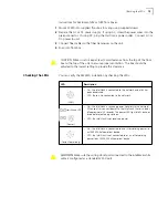
Check the LEDs.
Planning the Installation
When installed, the back of the IntelliJack extends into a wall or cubicle opening at
least 25mm. Because the depth of some wall and cubicle openings differ, observe
the following requirements and recommendations before installing the IntelliJack:
•
The NJ225 has been designed for installation into wall or cubicle openings that
conform to BSI standard BS 4664. Installation into openings not conforming to
this standard may be accomplished using a suitable mounting adapter plate.
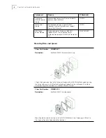
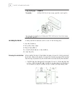
3Com Part Number:
3CNJMP-FR
Description:
IntelliJack NJ225 French-style raceway (goulotte) mounting plate
Mounting plate that enables the installation of an NJ225 IntelliJack in a French-style raceway
(locally called “goulotte”).
Summary of Contents for IntelliJack NJ225FX
Page 24: ...20 CHAPTER 1 INSTALLING THE INTELLIJACK ...
Page 34: ...30 CHAPTER 2 INSTALLING THE CONFIGURATION MANAGERS ...
Page 38: ...34 CHAPTER 3 USING THE LOCAL CONFIGURATION MANAGER ...
Page 74: ...70 CHAPTER 4 USING THE CENTRAL CONFIGURATION MANAGER ...
Page 86: ...Product Specifications 82 ...

