ZXR10 8900E series Core Switch Product Description
ZTE Confidential Proprietary
© 2013 ZTE CORPORATION. All rights reserved.
81
4.3
Hardware Boards
4.3.1
Switching Main Control Board
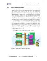
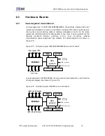
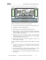
In actual application of ZXR10 8912E/8908E/8905E, the switching module and control
module are integrated on one main control board, including CPU subcard, switching chip,
clock system and monitoring subcard, realizing management control for the whole
system and switching function for data packets of line cards. It can be divided into the
following functional modules: switching, control, clock, monitoring, outband
communication, power supply and logic modules. Its principle diagram is as shown in
Figure 4-13.
Figure 4-13 Principle diagram of 8912E/8908E/8905E main control board
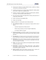
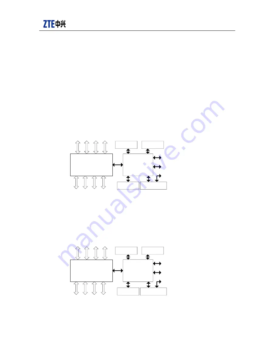
In actual application of ZXR10 8902E, the main control board realizes the control function.
Its principle diagram is as shown in Figure 4-14.
Figure 4-14 Principle diagram of 8902E main control board
CROSSBAR
CPU
syst em
SDRAM
BOOTROM
Consol e
i nt er f ace
MGT i nt er f ace
Hi gh- speed XAUI
i nt er f ace
Hi gh- speed XAUI
i nt er f ace
Cl ock
subcar d
Moni t or i ng
subcar d
I PMC i nt er f ace
CROSSBAR
CPU
syst em
SDRAM
BOOTROM
Consol e
i nt er f ace
MGT i nt er f ace
Cl ock
subcar d
Moni t or i ng
subcar d
I PMC i nt er f ace
GE i nt er f aces
GE i nt er f aces
Содержание ZXR10 8900E series
Страница 1: ...Operator Logo ZXR10 8900E series Core Switch Product Description ...
Страница 2: ......
Страница 10: ......

