ZXR10 8900E series Core Switch Product Description
ZTE Confidential Proprietary
© 2013 ZTE CORPORATION. All rights reserved.
V
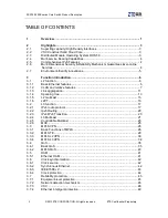
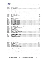
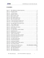
FIGURES
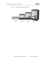
Figure 1-1 ZXR10 8900E series product appearance ........................................................... 2
Figure 3-1 MC-ELAM structure........................................................................................... 13
Figure 3-2 L2TP Networking ............................................................................................. 16
Figure 3-3 Architecture of MCE .......................................................................................... 25
Figure 3-4 MPLS working principle ..................................................................................... 27
Figure 3-5 MPLS header structure ..................................................................................... 28
Figure 3-6 Basic VPWS network model .............................................................................. 30
Figure 3-7 Basic VPLS network model ............................................................................... 32
Figure 3-8 H-VPLS networking with U-PW access ............................................................. 32
Figure 3-9 H-VPLS networking with QinQ access .............................................................. 33
Figure 3-10 Basic BGP MPLS VPN network model ............................................................ 34
Figure 3-11 end to end MPLS QoS .................................................................................... 41
Figure 3-12 SyncE synchronization .................................................................................... 43
Figure 3-13 IEEE 1588 synchronization ............................................................................. 44
Figure 3-14 SQA association ............................................................................................. 48
Figure 3-15 VSC system logic connection diagram ............................................................ 48
Figure 3-15 ZESR break alarm........................................................................................... 49
Figure 3-16 ZESS protection mechanism ........................................................................... 51
Figure 3-17 ZESR+ working principle ................................................................................. 51
Figure 3-18 PW single-hop redundancy protection ............................................................. 54
Figure 3-19 PW multi-hop redundancy protection .............................................................. 54
Figure 3-20 CE dual-homing to PE ..................................................................................... 55
Figure 3-21 UPE dual-homing to NPE ................................................................................ 56
Figure 3-22 Route switching diagram ................................................................................. 56
Figure 3-23 Label switching diagram .................................................................................. 57
Figure 3-24 TE FRR local link and node protection ............................................................ 58
Figure 3-25 CE dual-homing model .................................................................................... 59
Figure 3-26 Multi-Level Processing Procedure ......................
Error! Bookmark not defined.
Figure 3-27 sFlow Multi-level Architecture .......................................................................... 69
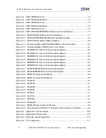
Figure 4-1 ZXR10 8912E appearance ................................................................................ 71
Figure 4-2 ZXR10 8912E structure ..................................................................................... 72
Figure 4-3 ZXR10 8908E appearance ................................................................................ 73
Содержание ZXR10 8900E series
Страница 1: ...Operator Logo ZXR10 8900E series Core Switch Product Description ...
Страница 2: ......
Страница 10: ......

