ZXR10 8900E series Core Switch Product Description
86
© 2013ZTE CORPORATION. All rights reserved.
ZTE Confidential Proprietary
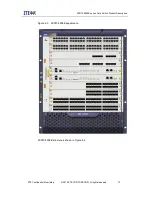
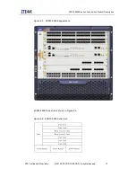
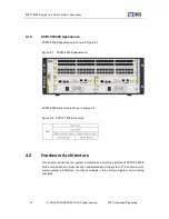
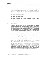
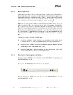
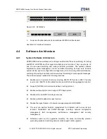
The panel diagram of 8902E main control board named 8902EMSC1A without Clock
synchronization is as shown.
Figure 4-20 8902EMSC1A main control board panel diagram
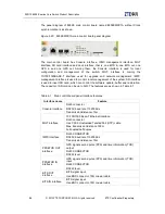
The main control board has Console interface, IPMC management interface, MGT
interface, SD card interface and clock interface, that is, one BITS in, one BITS out, one
GPS in and one GPS out. Among them, the Console interface is used for local
configuration and management of the switch; MGT interface is mainly the
10/100/1000BASE-T interface used for upgrade and network management; IMPC
management interface is used to monitor local management of the system; SD interface
is used to insert SD card, which can control the software update, buffer and restoration.
The capacity of SD card can be up to 32G. The features are as shown in Table 4-1.
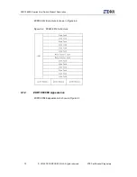
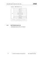
Table 4-1 Main control board panel interface features
Interface name
Feature
Console interface
RJ45 connector
RS232, baud rate 115200bit/s
Transmission distance<15m
MGT interface
10/100/1000 Base-T Ethernet interface
RJ45 connector
Use CAT-5 Unshielded Twisted Pair (UTP) cable
Max. transmission distance 100m
Full duplex/half duplex
IMPC interface
RJ45 CONNECTOR
RS232, baud rate 115200bit/s
Transmission distance<15m
PPS&TOD OUT
interface
GPS signal second pulse (PPS) and time information (TOD)
output
RJ45 CONNECTOR
RS422 level
PPS&TOD IN
interface
GPS signal second pulse (PPS) and time information (TOD)
input
RJ45 CONNECTOR
RS422 level
BITS OUT
interface
BITS signal input
Use BNC connector, 75Ω coaxial cable
BITS IN interface
BITS signal input
Use BNC connector, 75Ω coaxial cable
Содержание ZXR10 8900E series
Страница 1: ...Operator Logo ZXR10 8900E series Core Switch Product Description ...
Страница 2: ......
Страница 10: ......

