10
A
A
B
B
RC
MC
RO
E
Y
W/OB
C
R
C
R
ZN1
ZN2
ZN3
ZN4
ZN5
ZN6
ZN7
ZN8
ZN9
ZN10
RUN OPEN
RUN CLOSED
HP
DAMPER CONTROL BOARD LEGEND
A
B
C
E
F
G
D
A
R & C 24 volt Power Daisy Chained IN and OUT
B
Thermostat Terminals
C
Damper Board ID
D
Jumper for Heat Pump Operation
E
Damper Motor Terminals
F
Data Transmit / Receive IN
G
Date Transmit / Receive OUT
TERMINAL FUNCTIONS / CONNECTIONS
R / C
- 24 volt Power IN and OUT
R
- 24 volt Hot to Thermostat
C
- 24 volt Common to Thermostat
W/OB
- Heating Input / Reversing Valve Input
Y
- Cooling Input
E
- Emergency Heat Input (Heat Pump Only)
MC
- Motor Common
RO
- Run Open
RC
- Run Closed
A / B
- Data Transmit / Receive IN and OUT
DAMPER CONTROL BOARD CALL OUT AND CONFIGURATION
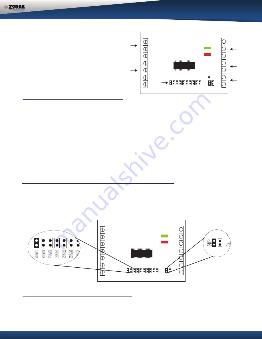
DAMPER CONTROL BOARD ADDRESSING / CONFIGURATION
Each damper control board must have a unique address from 1-10. To set the damper control board address there is a
jumper on the board. Find the first damper in the daisy chain and place the jumper on ZN1 for address #1. Go to the
second damper in the daisy chain and place the jumper on ZN2 for address #2. Continue addressing the damper control
boards in numerical order of the daisy chain wiring.
A
A
B
B
RC
MC
RO
E
Y
W/OB
C
R
C
R
ZN1
ZN2
ZN3
ZN4
ZN5
ZN6
ZN7
ZN8
ZN9
ZN10
RUN OPEN
RUN CLOSED
HP
A
A
B
B
RC
MC
RO
E
Y
W/OB
C
R
C
R
ZN1
ZN2
ZN3
ZN4
ZN5
ZN6
ZN7
ZN8
ZN9
ZN10
RUN OPEN
RUN CLOSED
HP
A
A
B
B
RC
MC
RO
E
Y
W/OB
C
R
C
R
ZN1
ZN2
ZN3
ZN4
ZN5
ZN6
ZN7
ZN8
ZN9
ZN10
RUN OPEN
RUN CLOSED
HP
Setting Damper Boards for Heat Pump Operation
When the GEN II-R controller is set up for Heat Pump operation, every damper board in the system needs to be
placed in heat pump mode. This allows the dampers boards to work with heat pump thermostats. Place the HP
jumper on both pins.


