Z8 Encore! XP F042A 8-Pin Development Kit
Quick Start Guide
QS005506-0111
Page 12 of 15
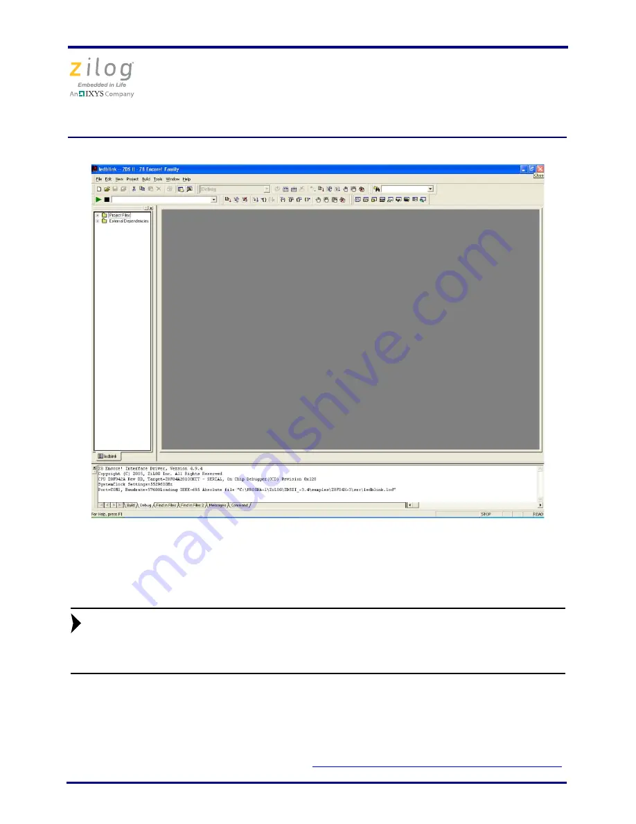
Figure 4. Zilog Developer Studio II Active Screen
12. Two LEDs on the development board begin blinking in sequence. If the LEDs do not
blink, repeat Step 3.
LED D2/PA0 is shared with the DBG pin. Zilog does not recommend having
the LED connected while connecting to the target or while in debug mode
(J3 should be OUT).
13. Press the
TEST
push button to change the sequence of the LEDs to blink in the opposite
direction.
For more information about using Zilog Developer Studio II and building projects for your
Z8 Encore! XP development kit, refer to the
ZDS II – Z8 Encore! User Manual (UM0130)
.
Note:


